Data transmitting system

a data transmission and data technology, applied in logic circuit coupling/interface arrangement, baseband system details, instruments, etc., can solve the problems of parasitic capacitor component in transmission lines, distortion of output signals, and increase parasitic capacitor components in transmission lines, so as to reduce signal coupling noise, shorten the transition time of signals, and inhibit the fluctuation of common mode voltage

Inactive Publication Date: 2010-05-20
DONGBU HITEK CO LTD
View PDF2 Cites 23 Cited by
  • Summary
  • Abstract
  • Description
  • Claims
  • Application Information

AI Technical Summary

Benefits of technology

[0009]An embodiment of the present invention provides a data transmitting system that reduces signal coupling noise due to parasitic capacitance in a MOS switch of a transmitter. Embodiments can shorten a transition time of a signal and match noise voltage induced to a differential terminal, making it possible to inhibit fluctuation of the common mode voltage.

Problems solved by technology

The differential voltage driving scheme remarkably reduces the distortion due to noise of the transmission signals as compared to the single voltage driving scheme, but has problems in that an interference phenomenon occurs between the transmission lines and that the parasitic capacitor component in the transmission lines is increased.
However, the MOS switch tends to have large parasitic capacitance, resulting in the parasitic capacitor component in the transmission lines.
Therefore, the input logic signals induce a coupling noise in the output small signals to cause the distortion of the output signal.
Thereby, the trigger time of the output signal is long and the degradation of transmission speed occurs.
In addition, the coupling noise voltages are induced differently to the differential voltage terminal, such that the common mode voltage fluctuates.

Method used


Image

  • Data transmitting system
  • Data transmitting system
  • Data transmitting system

Examples


Embodiment Construction

[0014]A data transmitting system according to an embodiment will be described in detail with reference to the accompanying drawings.

[0015]Hereinafter, the detailed description of a related known functions or configurations that may unnecessarily obscure the subject matter of the present invention in describing the present invention will be omitted. Therefore, only the core components, which are directly related with the technical idea of the present invention, will be described.

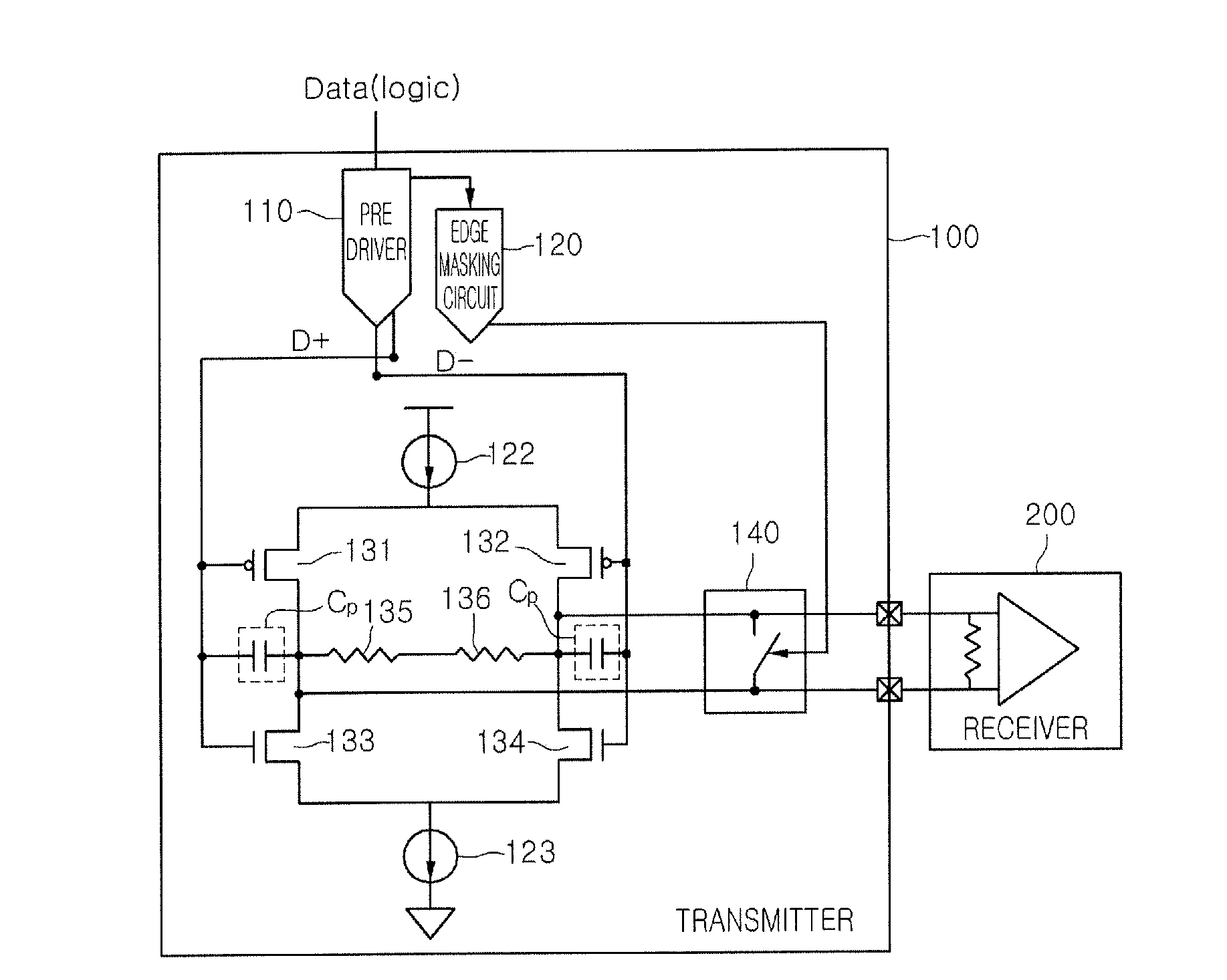
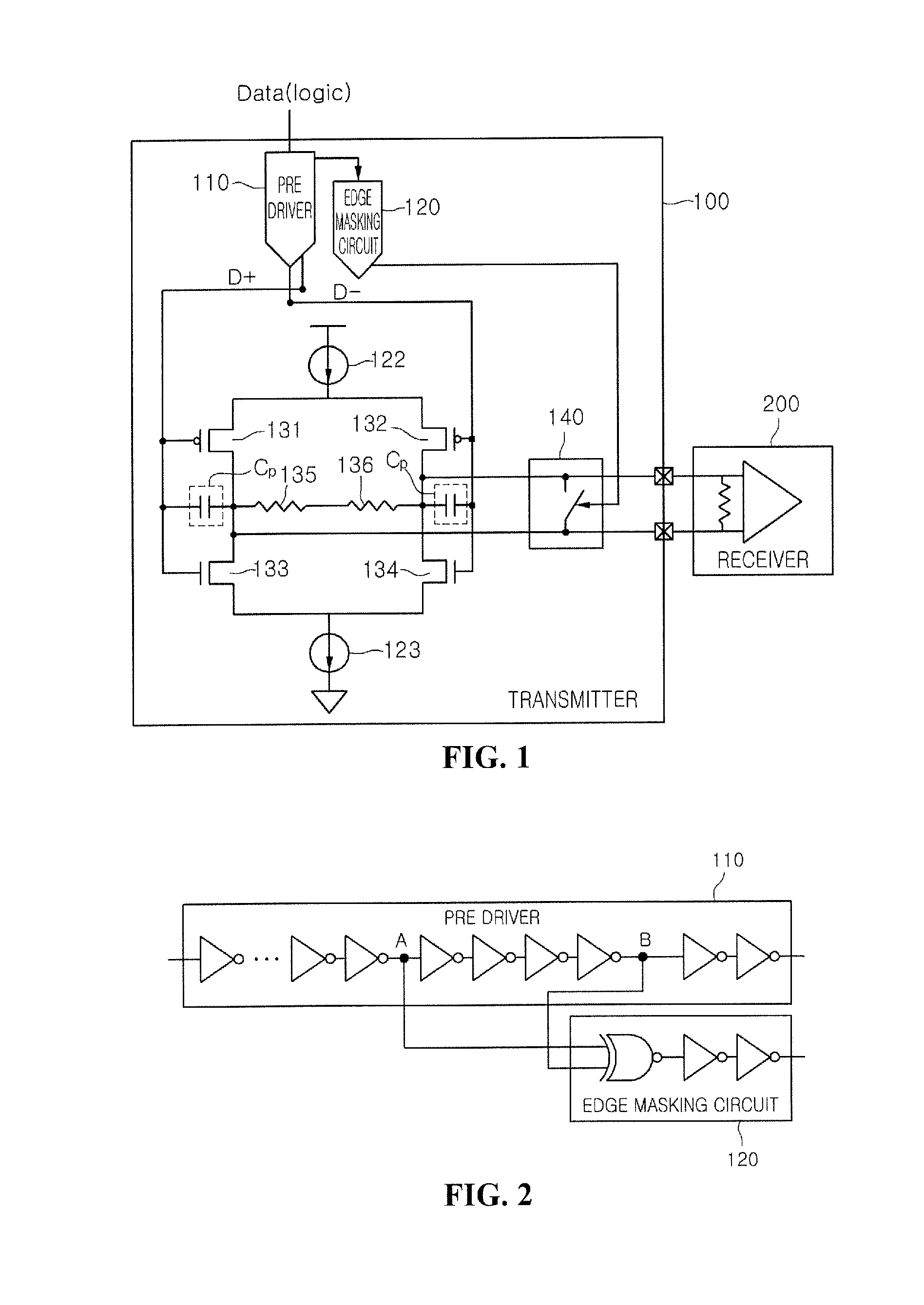
[0016]FIG. 1 is a block diagram of a data transmitting system according to an embodiment. FIG. 2 is a block diagram providing a more detailed view of a pre-driver 110 and an edge masking circuit 120 of a transmitter 100 in accordance with an embodiment of a data transmitting system.

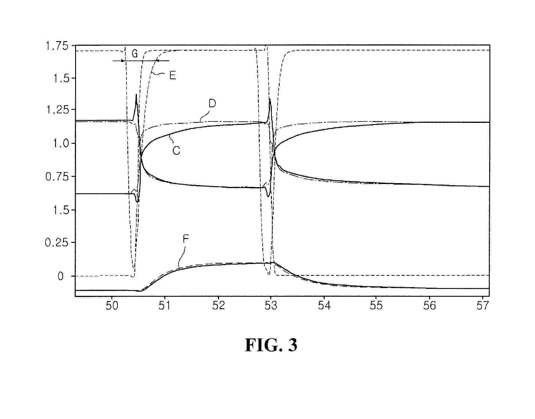
[0017]In addition, FIG. 3 is a timing diagram graphically showing a signal form processed in the data transmitting system according to an embodiment.

[0018]Referring to FIG. 1, the data transmitting system according to an embodiment...


PUM


Abstract

A data transmitting system is provided that includes a transmitter that suppresses coupling noise by being operated using a differential voltage driving scheme at the time of transmitting data and being operated using a common voltage driving scheme by equalizing potential of a pair of transmission lines during a transition interval; and a receiver that is connected to the transmitter through the pair of transmission lines and recovers the data by sensing the voltage difference in signals of the pair of transmission lines.

Description

CROSS-REFERENCE TO RELATED APPLICATION[0001]This application claims the benefit under 35 U.S.C. §119 of Korean Patent Application No. 10-2008-0113547, filed Nov. 14, 2008, which is hereby incorporated by reference in its entirety.BACKGROUND[0002]Two schemes have typically been used when transmitting data through a transmission line that connects between two or more semiconductor chips.[0003]The first scheme converts and transmits data signals into a difference in a current intensity that is output to the transmission line.[0004]The second scheme converts data into a voltage difference at a transmitting side, carries the voltage difference on the transmission line, detects the voltage difference at a receiving side, and recovers the data.[0005]The above-mentioned voltage driving scheme may be classified into a single voltage driving scheme that assigns one transmission line for each data according to the number of lines receiving one bit data and provides the data as the magnitude of...

Claims


Application Information

Patent Timeline
Patent Type & Authority Applications(United States)
IPC IPC(8): H04L25/03
CPCH04L25/0272H04L25/085H04L25/028H04L25/0276G11C7/10G11C5/14
Inventor JANG, DAE JOONG
Owner DONGBU HITEK CO LTD
Why Eureka
Try Eureka