Cylinder for a printing unit of a printing machine and method for replacing a sleeve for such the cylinder

a printing unit and printing machine technology, applied in the direction of printing, rotary presses, other printing apparatus, etc., can solve the problems of hardly being automated, changes in adjustments, and considerable problems, and achieve the effect of convenient and fast replacement of the printing sleeves and good printing quality

Inactive Publication Date: 2009-08-13
MULLER MARTINI HLDG
View PDF2 Cites 13 Cited by
  • Summary
  • Abstract
  • Description
  • Claims
  • Application Information

AI Technical Summary

Benefits of technology

[0008]It is an object of the present invention to provide a cylinder of the aforementioned type, which permits an easier and faster replacement of the printing sleeve while nevertheless ensuring a good printing quality. In particular, it should be easy to automate the operation of clamping down and releasing the printing sleeve. It is furthermore an object of the invention to specify corresponding methods for replacing printing sleeves.

Problems solved by technology

In order to securely attach such a printing sleeve to the support shaft and to maintain good printing quality, it is important to ensure a sufficient centering as well as a uniform torque transfer from the support shaft to the printing sleeve which, however, is very involved if a force must be exerted separately onto the tensioning elements and can hardly be automated.
Compressible layers of this type, however, have the disadvantage that the printing sleeves are pushed out of their concentric position as a result of the high linear forces exerted during the offset printing, meaning the high forces for pressing the cylinder against the contact line, thereby resulting in changes to the adjustments and thus also to considerable problems during the printing operation.
Ring-shaped tensioning elements of this type, however, do not have sufficient rotational accuracy and are relatively expensive to install / remove.
If the pressure of the medium drops, then the printing sleeve immediately detaches itself from the cylinder core, which can considerably interfere with the printing process.
The additional arrangement of a clamping sleeve and the necessary fitting on of the stamping die by using an air cushion, however, results in a relatively involved device and method.
As a result, the clamping sleeve is clamped to the drive shaft section, so that immediately thereafter the first fixation device is secured in axial direction and any further transfer of force to the second fixation device is impossible.
The danger consequently exists that the clamping sleeve and thus the stamping die can only be securely mounted on one side, which accordingly hinders or even prevents a following stamping operation.

Method used


Image

  • Cylinder for a printing unit of a printing machine and method for replacing a sleeve for such the cylinder
  • Cylinder for a printing unit of a printing machine and method for replacing a sleeve for such the cylinder
  • Cylinder for a printing unit of a printing machine and method for replacing a sleeve for such the cylinder

Examples


Embodiment Construction

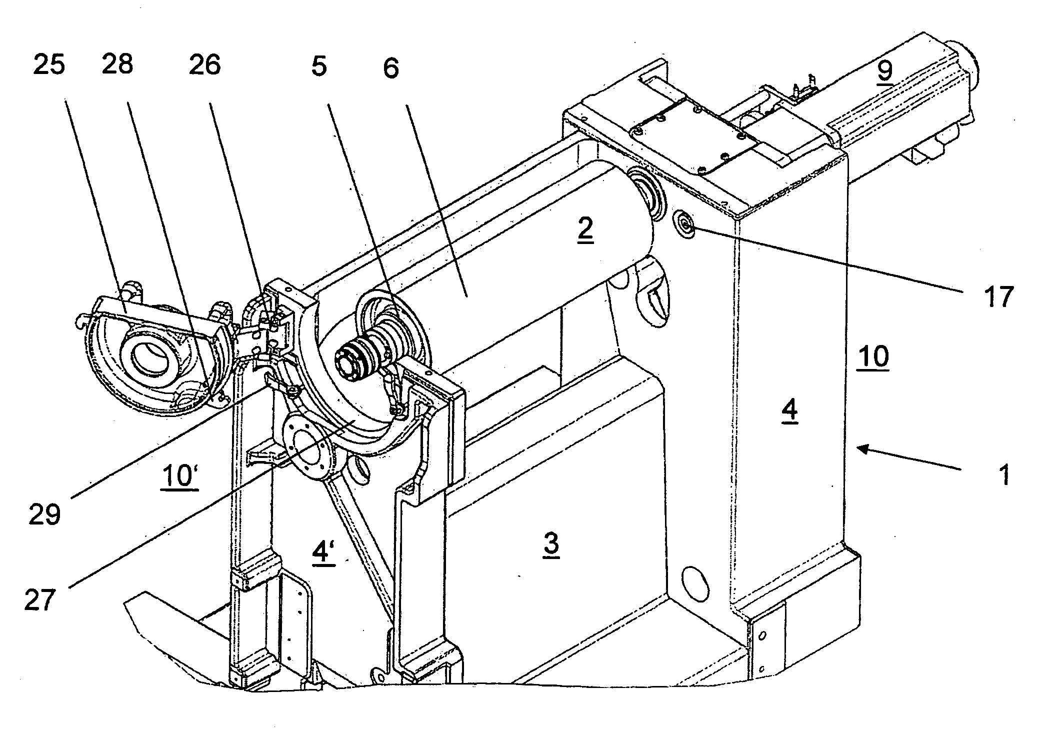
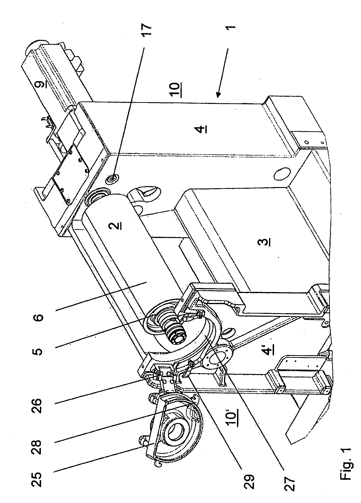
[0030]Referring to FIG. 1, there is shown a perspective view of an embodiment of a printing unit 1 for an offset printing machine, restricted to the components that are essential to understanding the invention. The printing unit 1 includes, among other things, a cylinder 2, wherein the illustrated embodiment shows a rubber-blanket cylinder. The printing unit includes a housing 3 with two side panels 4, 4′, designed for positioning the cylinder 2. Additional components that also belong to the printing unit 1, such as plate cylinders and counter-pressure cylinders as well as the ink and coloring units, have been omitted for reasons of clarity.

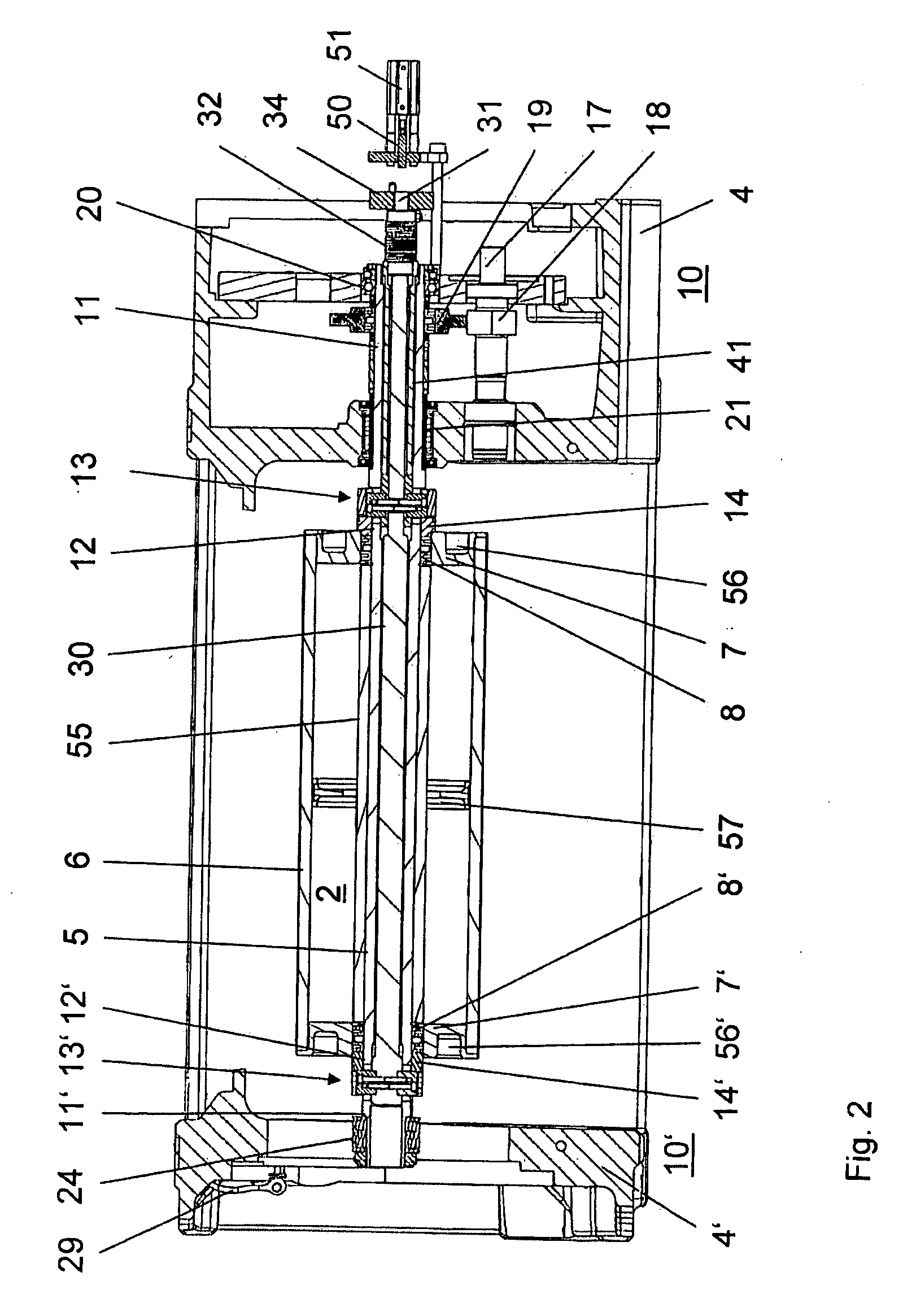
[0031]The cylinder 2 includes a cylinder core in the form of a support shaft 5, which is detachably connected to a format part embodied as printing sleeve 6. The printing sleeve 6 is provided on each end with respectively one integral support ring 7, 7′ which, in the fully assembled state, is clamped so as to rotate along with the support shaft 5...


PUM


Abstract

A cylinder for a printing unit of a printing machine includes a hollow support shaft with first and second tensioning elements arranged thereon at a distance to each other. A replaceable printing sleeve is positioned on the support shaft. First and second force transfer elements respectively cooperate with the first and the second tensioning element for clamping down and releasing the printing sleeve. An operating mechanism is arranged on the inside of the hollow support shaft and is operatively connected to the two force transfer elements. The operating mechanism includes at least one energy-storage element for tightening and releasing the two tensioning elements.

Description

CROSS-REFERENCE TO RELATED APPLICATION[0001]This application claims the priority of European Patent Application No. 08405036.8, filed on Feb. 12, 2008, the subject matter of which is incorporated herein by reference.BACKGROUND OF THE INVENTION[0002]The invention relates to a cylinder for a printing unit of a printing machine, the cylinder having a support shaft with a first and a second tensioning element arranged thereon at a distance to each other, on which a replaceable printing sleeve is positioned with the aid of a first and a second force transfer element that respectively cooperates with the first and / or second tensioning element for clamping down and releasing the printing sleeve. The invention furthermore relates to a method for replacing a printing sleeve on such a cylinder.[0003]In order to process successively following, different printing jobs, printing machines must be retrofitted accordingly by replacing the cylinders of the printing units. To avoid such an expensive ...

Claims


Application Information

Patent Timeline
Patent Type & Authority Applications(United States)
IPC IPC(8): B41F13/10B41F13/20
CPCB41F13/08B41P2227/21B41P2217/15
Inventor BEYERSDORFF, STEFAN
Owner MULLER MARTINI HLDG
Why Eureka
Try Eureka