
Apparatus, circuit and method of monitoring circuit characteristic

Active Publication Date: 2009-08-13
NEC CORP
View PDF9 Cites 2 Cited by
  • Summary
  • Abstract
  • Description
  • Claims
  • Application Information

AI Technical Summary

Benefits of technology

[0015]According to one exemplary aspect of the present invention, an apparatus includes a current source, a current monitor circuit which monitors a current amount of the current source, and outputs a current amount signal corresponding to the current amount being monitored, a counter circuit w

Problems solved by technology

Scaling down a semiconductor integrated circuit and increasing its integration level may increase the power consumption.
The increase of the power consumption in the semiconductor integrated circuit may increase a temperature of the semiconductor integrated circuit.
The increase of the temperature may decrease the life of elements of the semiconductor integrated circuit.
The decrease in the life of the elements leads to a decreasing reliability of an apparatus including the semiconductor integrated circuit.
The increase of the power consumption of the semiconductor integrated circuit may impose a problem that the required power may approach the limit of a power supply facility owned by a customer.
However, as a speed and performance is increased in an LSI (Large Scale Integrated circuit), such techniques may not restrain the increasing power consumption when the clock frequency is increased or a multicore is adopted in the processor.

Method used


Image

  • Apparatus, circuit and method of monitoring circuit characteristic
  • Apparatus, circuit and method of monitoring circuit characteristic
  • Apparatus, circuit and method of monitoring circuit characteristic

Examples


first exemplary embodiment

1. First Exemplary Embodiment

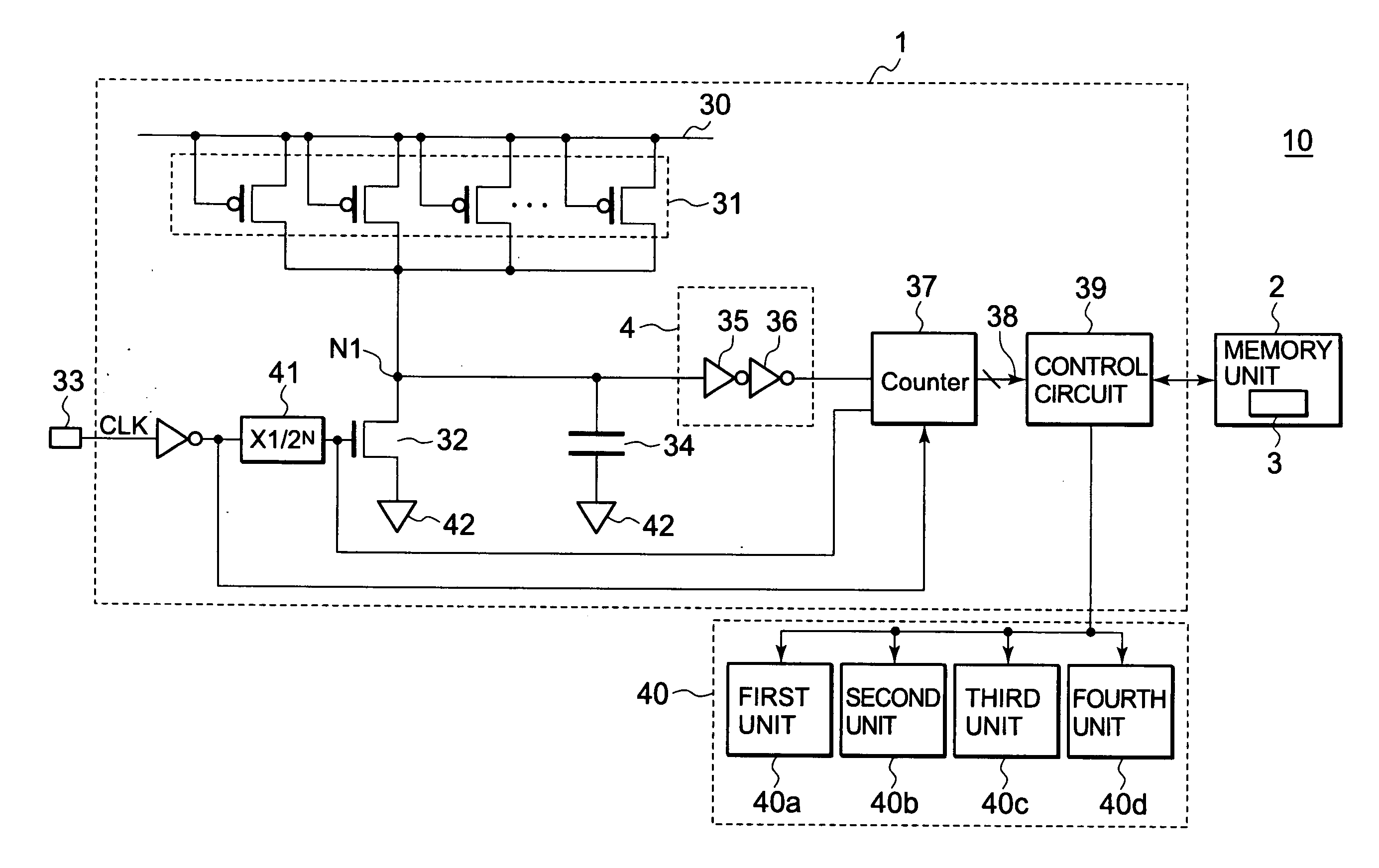
[0035]FIG. 4 is an example of a block diagram of a semiconductor integrated circuit 10 of an exemplary first embodiment.

[0036]The semiconductor integrated circuit 10 of the exemplary first embodiment includes a monitor circuit 1, a memory unit 2 including a power supply voltage setting table 3, and a circuit unit 40. The monitor circuit 1 controls the power supply voltage supplied to the circuit unit 40. However, a parameter being controlled by the monitor circuit 1 is not limited to the power supply voltage. For example, the operation frequency or the like of the circuit unit 40 may be controlled by the monitor circuit 1. The circuit unit 40 includes a plurality of units (a first unit 40a, a second unit 40b, a third unit 40c, and a fourth unit 40d). The monitor circuit 1 determines power supply voltage values supplied to the respective units.

[0037]The monitor circuit 1 includes a leak current source 31 connected to a power supply 30, a frequency divider...

second exemplary embodiment

2. Second Exemplary Embodiment

[0054]FIG. 7 is an example of a block diagram of the monitor circuit 1 in a semiconductor integrated circuit 10 of the second exemplary embodiment.

[0055]For the above described first exemplary embodiment, the monitor circuit 1 includes a leak current source 31 including a plurality of PMOS transistors and a control transistor 32 configured by an NMOS transistor. The monitor circuit 1 of the second exemplary embodiment includes a current source 46 including a plurality of NMOS transistors and a control transistor 47 configured by a PMOS transistor. In addition, the counter control circuit 4 includes three inverters, and specifically inverter 43, inverter 44 and inverter 45.

[0056]In the monitor circuit 1 of the second exemplary embodiment, the counter 37 measures a time until the charges in the capacitor 34 are discharged to a predetermined value (i.e., Vth). A frequency divider 48 generates a dividing clock based on the controlling clock CLK similarly to...

third exemplary embodiment

3. Third Exemplary Embodiment

[0059]FIG. 9 is an example of a block diagram of the monitor circuit 1 of the third exemplary embodiment. The monitor circuit 1 of the third exemplary embodiment includes a wiring 49 between a leak current source 31 and a capacitor 34.

[0060]The wiring 49 has a wiring length, and thus becomes a resistance. Therefore, a time until when the capacitor 34 is charged with a current varies depending on the resistance of the wiring 49. The semiconductor process variation influences the resistance of the wiring 49. By adding the wiring 49, the monitor circuit 1 of the third exemplary embodiment may observe the semiconductor process variation including the semiconductor process level and the wiring resistance variation.

[0061]The wiring resistance correlates to the delay amount. Therefore, the power supply voltage and the clock frequency may be controlled by the count value 38 of the counter 37. In the third exemplary embodiment, the capacitor 34 may be configured ...


PUM


Abstract

An apparatus includes a current source, a current monitor circuit which monitors a current amount of the current source, and outputs a current amount signal corresponding to the current amount being monitored, a counter circuit which counts a count value based on the current amount signal, the count value corresponding to a period being taken until when the current amount reaches a predetermined value, and a control circuit which modifies an operation parameter for operating a circuit unit according to the count value.

Description

INCORPORATION BY REFERENCE[0001]This application is based upon and claims the benefit of priority from Japanese patent application No. 2008-030701, filed on Feb. 12, 2008, the disclosure of which is incorporated herein in its entirety by reference.BACKGROUND OF THE INVENTION[0002]1. Field of the Invention[0003]The present invention relates to a monitor circuit and relates, in particular, to technology of controlling a resource (such as a power supply voltage and a clock frequency, for example) with a monitor circuit to reduce power consumption.[0004]2. Description of Related Art[0005]Scaling down a semiconductor integrated circuit and increasing its integration level may increase the power consumption. The increase of the power consumption in the semiconductor integrated circuit may increase a temperature of the semiconductor integrated circuit. The increase of the temperature may decrease the life of elements of the semiconductor integrated circuit. The decrease in the life of the ...

Claims


Application Information

Patent Timeline
IPC IPC(8): G01R13/04
CPCH03K19/0016
Inventor KAJITA, MIKIHIRO
Owner NEC CORP
Learn More