
Method and apparatus for reduced coupling and interference between antennas

a technology of coupling and interference, applied in the direction of antenna coupling, antenna details, antennas, etc., can solve the problems of serious challenges in designing an antenna for operation near a large mounting structure or other antenna, severe distortion of electrical parameters of individual antennas radiating in multiple directions, and urgently need to improve antenna configuration. , to achieve the effect of improving the performance of the antenna

Inactive Publication Date: 2009-08-13
PENN STATE RES FOUND
View PDF10 Cites 15 Cited by
  • Summary
  • Abstract
  • Description
  • Claims
  • Application Information

AI Technical Summary

Benefits of technology

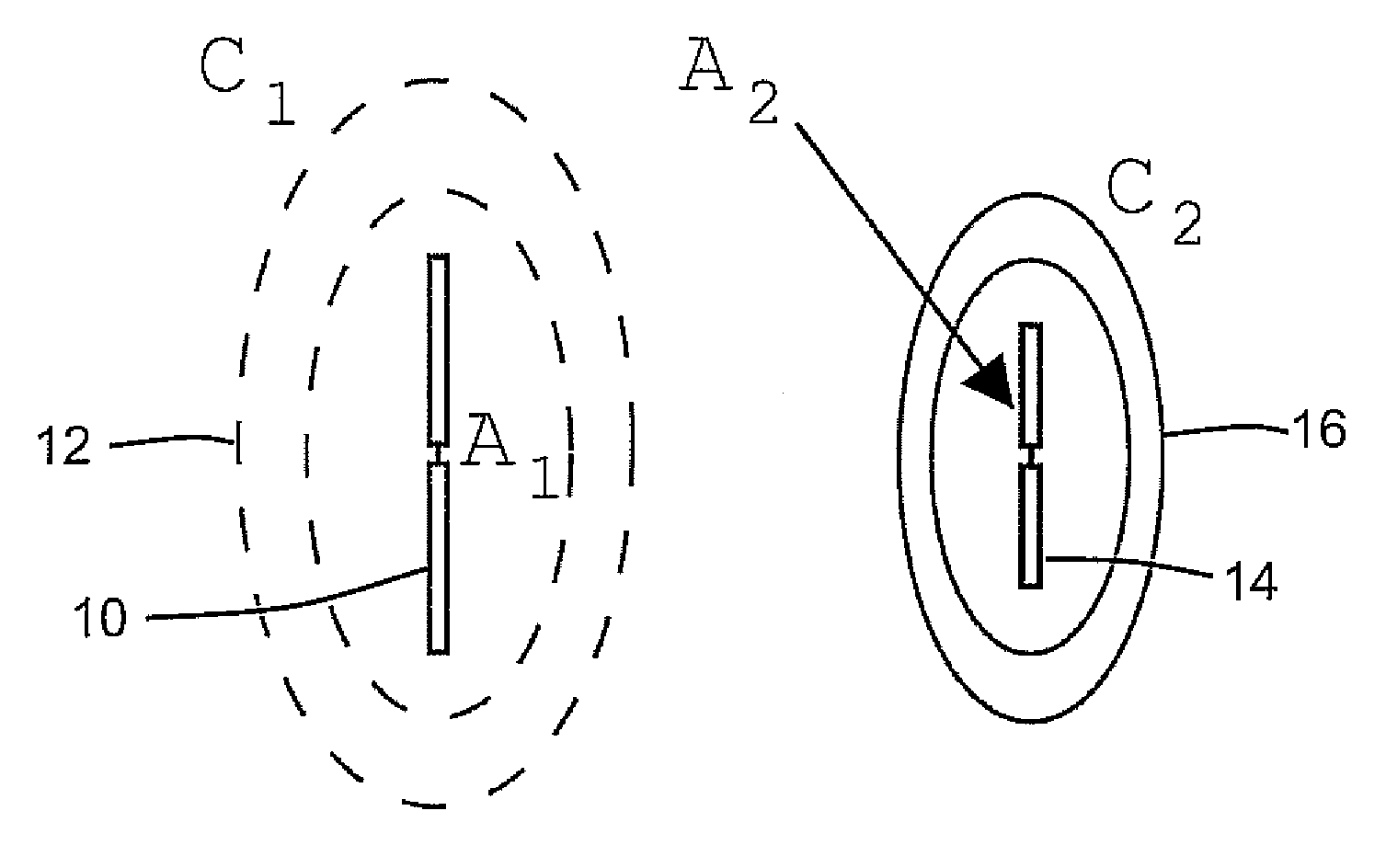
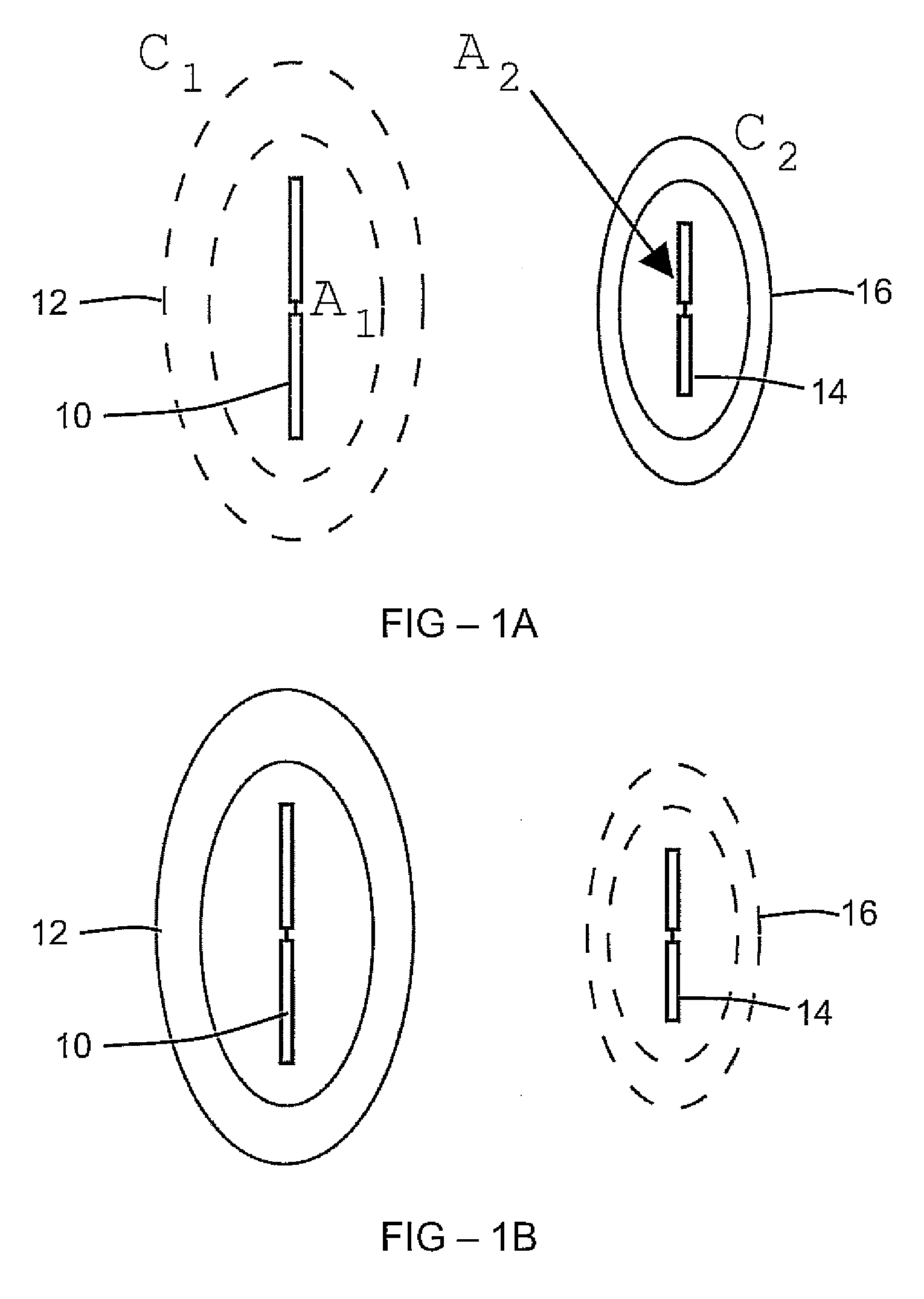
[0006]In examples of the present invention, electromagnetic cloaks are used as shielding devices which enable improved antenna performance, particularly in highly scattering, multiple-antenna configurations. An antenna may be enclosed in an electromagnetic cloak (hereinafter “cloak”), such as a metamaterial or other dispersive material, which is designed to operate as a cloak at the transmitting frequency (and / or receiving frequency) of one or more neighboring antennas.
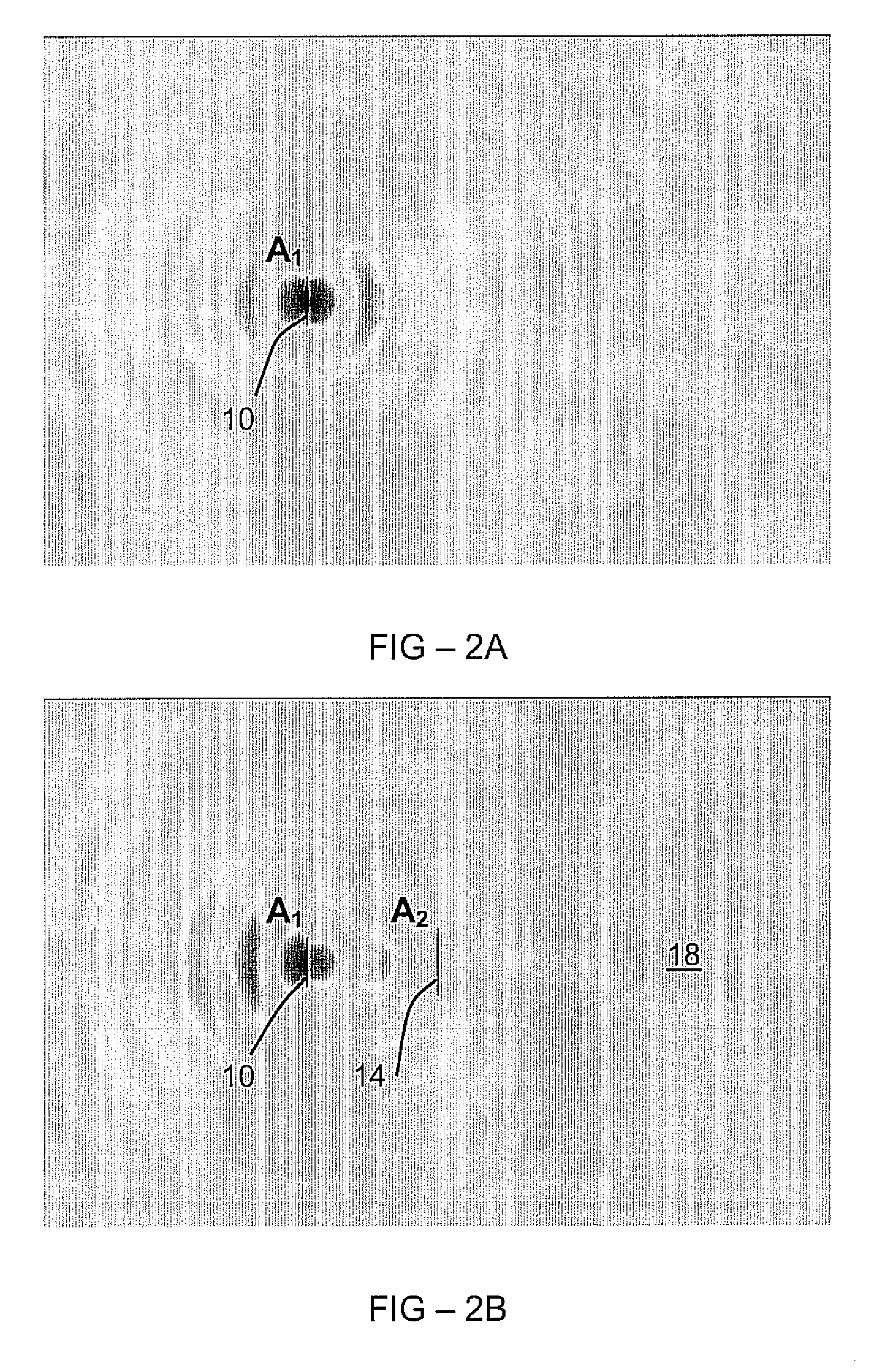
[0007]Further, the loading effect of an electromagnetic radiation scattering object (“scatterer”) proximate to a radiating antenna can be reduced or eliminated by enclosing the scatterer with an electromagnetic cloak.

Problems solved by technology

Designing an antenna for operation near a large mounting structures or other antenna is a serious challenge.
Moreover, near-field mutual coupling effects can severely distort the electrical parameters for individual antennas radiating in multiple-antenna environments.
Hence, improved antenna configurations are urgently required.

Method used


Image

  • Method and apparatus for reduced coupling and interference between antennas
  • Method and apparatus for reduced coupling and interference between antennas
  • Method and apparatus for reduced coupling and interference between antennas

Examples


Embodiment Construction

[0014]Examples of the present invention include methods and apparatus for reducing, and in some cases substantially eliminating, coupling and interference effects among multiple antenna elements located in proximity to each other. Shielding from interference is achieved by using electromagnetic cloaks, for example cloaks formed using a metamaterial. By enclosing individual antennas in properly designed electromagnetic cloaks, an antenna operating at one frequency does not present interference to other antennas operating at different frequencies. Moreover, an object in close proximity to an operating antenna can be cloaked so that it has no effect on either the near-field or far-field distribution of the antenna.

[0015]Applications include the mitigation of co-site interference, which typically occurs when multiple antennas are employed in a limited space. Wireless handsets may include several antennas to meet the requirements for one or more wireless communication standards. A ship o...


PUM


Abstract

Examples of the present invention include antennas and scattering elements having a metamaterial cloak configured so as to reduce effects on the operating parameters of a nearby antenna. For example, an antenna has an antenna frequency, and a cloak is disposed around the antenna having a frequency range in which the cloak is operative. The antenna frequency can lie outside the frequency range of the cloak, whereas the frequency of a second antenna lies within the frequency range of the cloak. In this case, the antenna is cloaked relative to the second antenna.

Description

REFERENCE TO RELATED APPLICATION[0001]This application claims priority to U.S. Provisional Patent Application Ser. No. 61 / 026,880, filed Feb. 7, 2008, the entire contents of which are incorporated herein by reference.GRANT REFERENCE[0002]This invention was made with government support under Grant No. DMR-0213623 awarded by the National Science Foundation (NSF). The government has certain rights in the invention.FIELD OF THE INVENTION[0003]The invention relates to antennas, in particular to improvement of antenna performance.BACKGROUND[0004]Designing an antenna for operation near a large mounting structures or other antenna is a serious challenge. For antennas mounted on large platforms such as ships or aircraft, objects part of the host structure may cast deep shadows in the forward direction of the radiation patterns. Moreover, near-field mutual coupling effects can severely distort the electrical parameters for individual antennas radiating in multiple-antenna environments.[0005]H...

Claims


Application Information

Patent Timeline
Patent Type & Authority Applications(United States)
IPC IPC(8): H01Q15/00H01Q5/10
CPCH01Q15/0086H01Q1/521
Inventor WERNER, DOUGLAS H.KWON, DO-HOON
Owner PENN STATE RES FOUND
Learn More