
Light fixture and reflector assembly for same

Active Publication Date: 2009-08-13
LSI INDS
View PDF26 Cites 10 Cited by
  • Summary
  • Abstract
  • Description
  • Claims
  • Application Information

AI Technical Summary

Benefits of technology

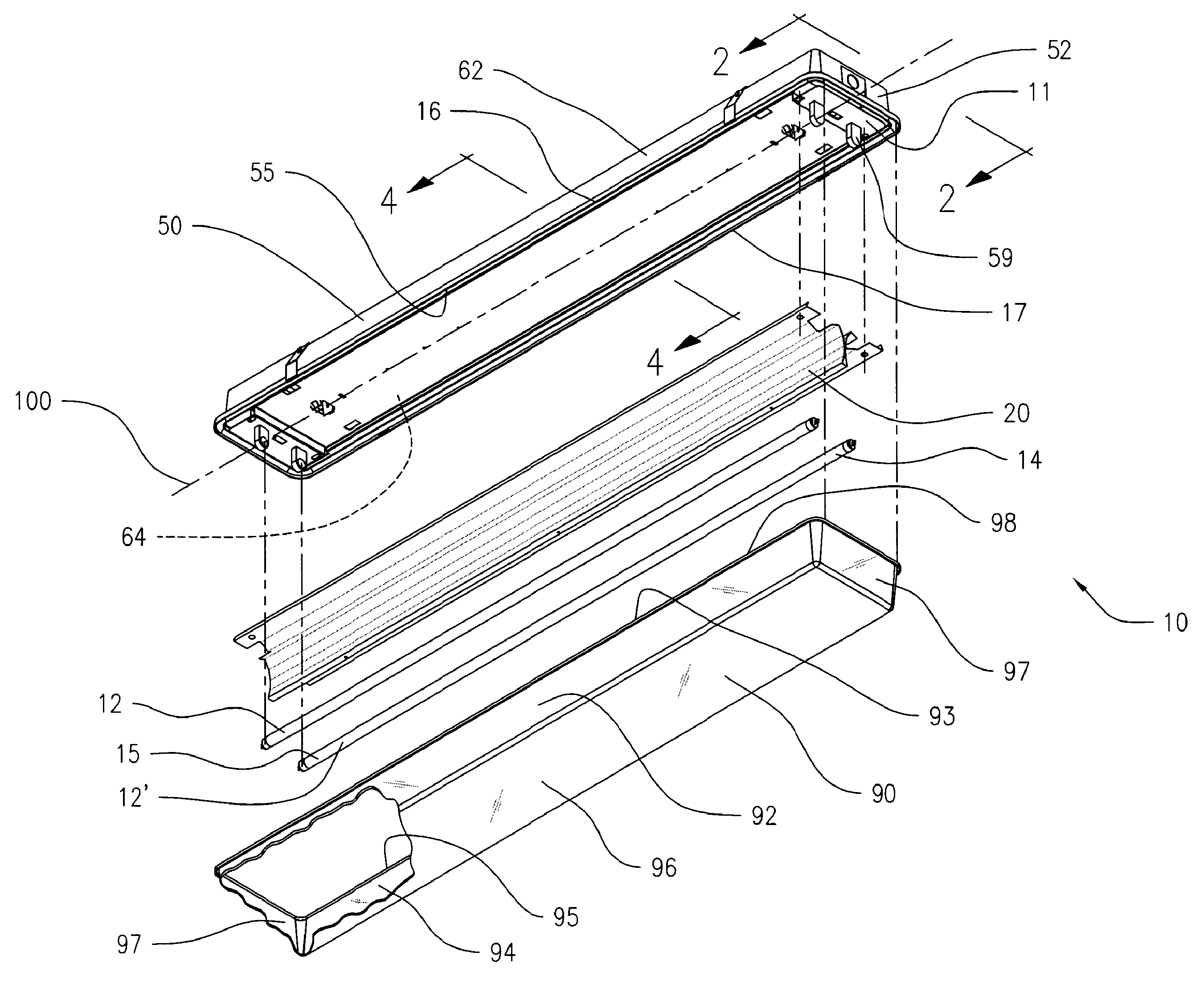
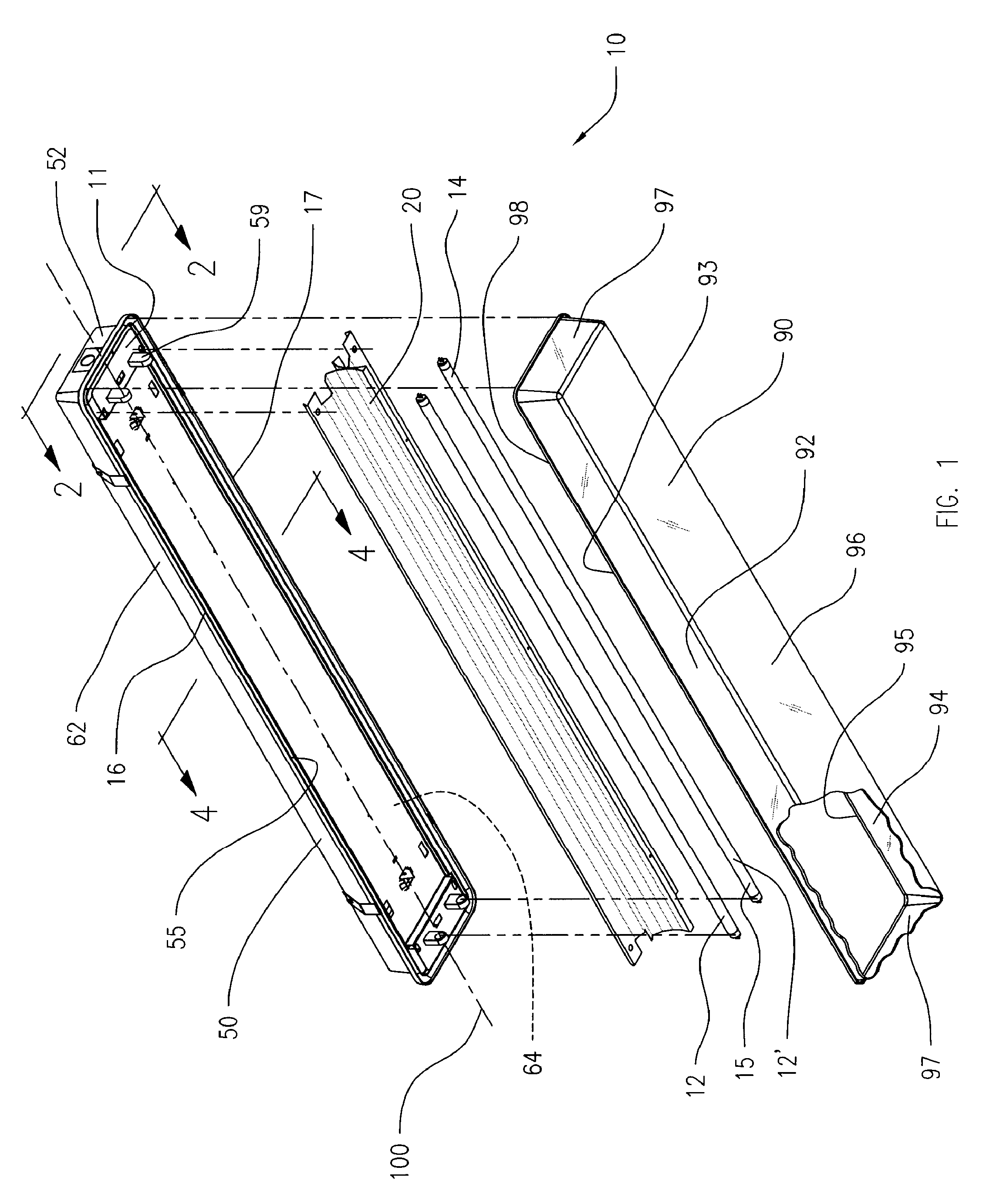
[0006]The present invention relates to a light fixture, or troffer, for efficiently distributing light emitted by a light source into an area to be illuminated. The light fixture can provide a more uniform lighting pattern, and allow for use of fewer of the light fixtures, by projecting or reflecting more of the radially emitted light from the lamp into a horizontal direction at higher angles from nadir, and toward the areas laterally remote from the light fixture.
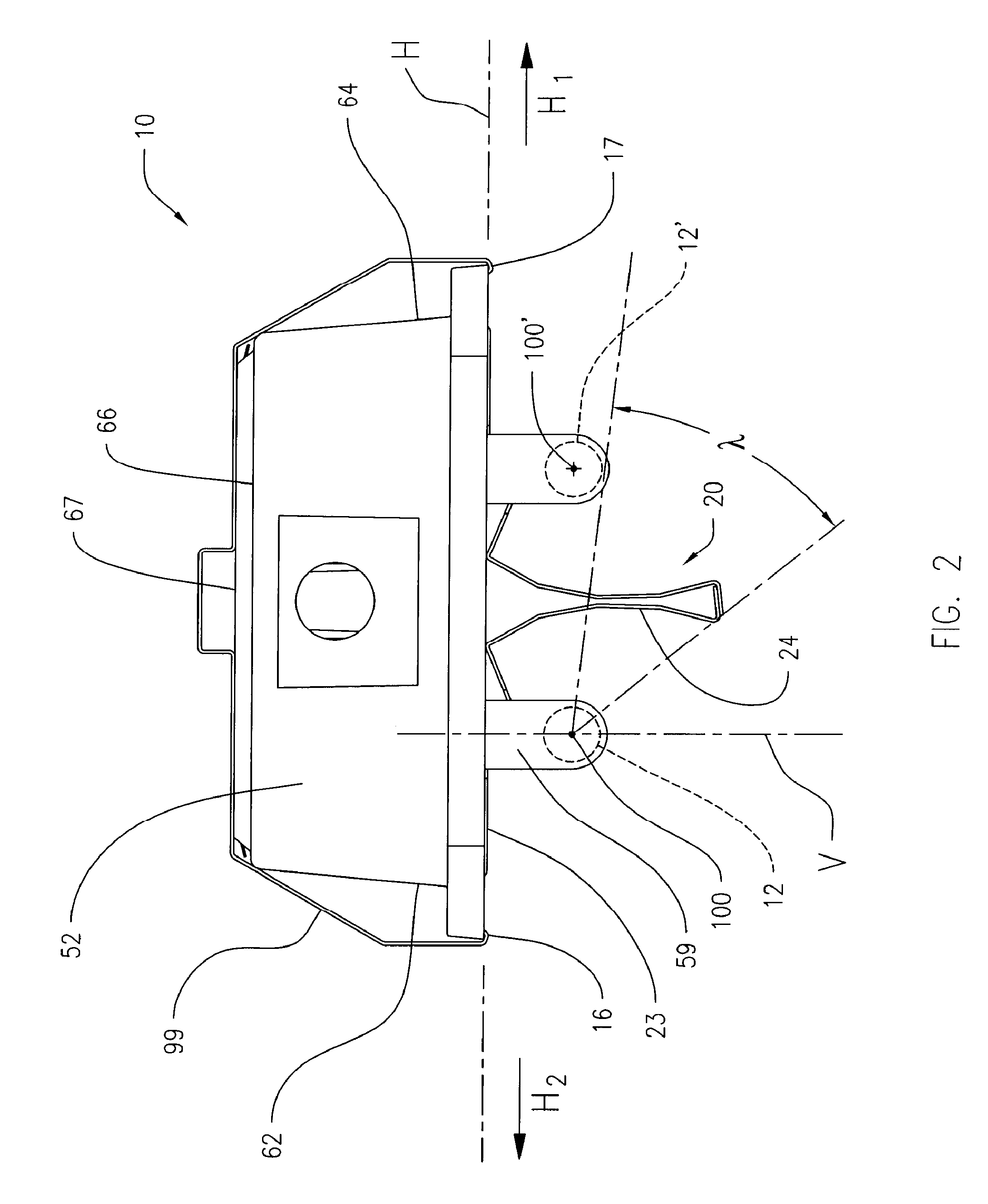
[0011]In another aspect of the invention, the light fixture further comprises a second reflector element and a second lamp, wherein the first and second reflector elements are associated to form a reflector assembly, and wherein the reflector assembly is disposed between the two lamps. The reflector assembly is configured to receive light that is emitted from one lamp toward the reflector surface disposed between the two lamps, and to reflect the incident light away from the reflector to an area laterally remote from the light fixture. In another aspect of the invention, the reflector increases the amount of light emitted and reflected to the areas below and laterally remote from the light fixture.
[0019]In another aspect of the invention, the light fixture further includes a domed lens positioned over and containing the extending reflector portions and the elongated lamps. The lens is preferably detachably secured to a portion of the housing. The lens in one aspect helps to protect the lamp from the environment, and in another aspect, can be configured with optical features which can bend and refract the light emitted from the lamp and reflected by the reflector assembly.

Problems solved by technology

However, energy consumption, performance and fixture costs have identified a need for improved lighting fixtures and performance in this usage, to obtain the required lighting levels with fewer fixtures.
This can result in uneven lighting, and areas of significantly less lighting remote from the light fixture or at an area between adjacent light fixtures.

Method used


Image

  • Light fixture and reflector assembly for same
  • Light fixture and reflector assembly for same
  • Light fixture and reflector assembly for same

Examples


Embodiment Construction

[0031]The present invention is more particularly described in the following exemplary embodiments that are intended as illustrative only since numerous modifications and variations therein will be apparent to those skilled in the art. As used herein, “a,”“an,” or “the” can mean one or more, depending upon the context in which it is used.

[0032]As used herein, the direction or orientation “horizontal” is intended to mean a direction or orientation along the longitudinal axis of the elongated lamp, while the direction or orientation “vertical” is intended to mean a direction or orientation perpendicular to the longitudinal axis of the longitudinal lamp.

[0033]As described herein, light or a portion thereof that is emitted or reflected in a horizontal direction can include light that is emitted or reflected in a direction at an angle to the horizontal direction, and having a horizontal directional vector and a vertical directional vector.

[0034]As used herein, the term “nadir” is typicall...


PUM


Abstract

A light fixture useful in the lighting of parking garages, including a base, a reflector element and at least one light-emitting lamp. The reflector element includes a reflector portion that extends vertical from the base to a distal edge that extends beyond the lamp. The extending reflector portions include a plurality of planer panels positioned in a plane at an angle that faces toward the lamp. A portion of the emitted light is reflected by the extending reflector portion in the opposed horizontal direction away from the fixture at a reflected angle from nadir that is greater than the emitted angle. The light fixture provides a uniform lighting pattern that allows for using fewer of the light fixtures, by projecting or reflecting emitted light horizontally at very high angles from nadir, and delivering more light to areas laterally remote from the fixture, and potentially using less energy.

Description

BACKGROUND OF THE INVENTION[0001]The present invention generally relates to light fixtures for illuminating architectural spaces. The invention has particular application in light fixtures using fluorescent lamps, such as the T5 linear fluorescent lamp, as the light source.[0002]Numerous light fixtures for architectural lighting applications are known. In conventional parking garages and lots, low wattage high intensity discharge (HID) light fixtures and lamps have been the norm. However, energy consumption, performance and fixture costs have identified a need for improved lighting fixtures and performance in this usage, to obtain the required lighting levels with fewer fixtures.[0003]Another light fixture presently used in a typical parking lot and warehouse environment comprises a troffer with at least one fluorescent lamp and a translucent lens shielding the lamp. The troffer includes an elongated fixture support, a pair of sockets at opposite ends to secure and provide power to ...

Claims


Application Information

Patent Timeline
IPC IPC(8): F21S4/00F21V7/00
CPCF21S8/06F21V7/005F21Y2113/00F21Y2103/00F21V7/04
Inventor EYNDEN, JAMES G. VANDEN
Owner LSI INDS
Learn More