
Method, apparatus and program for speech synthesis

a speech synthesis and program technology, applied in the field of speech synthesis technique, can solve the problems of significant deterioration in sound quality, lowered precision of pitch synchronization position, and deterioration of sound quality of synthesized speech, and achieve the effect of smooth concatenation, high sound quality and high sound quality

Active Publication Date: 2009-08-13
NEC CORP
View PDF17 Cites 18 Cited by
  • Summary
  • Abstract
  • Description
  • Claims
  • Application Information

AI Technical Summary

Benefits of technology

[0111]According to the present invention, the sampling rate conversion ratio, optimum for achieving the high sound quality, is computed based on the pitch frequency and on the position of pitch synchronization, even in case the position of pitch synchronization is controlled with the computation amount smaller than in case sampling rate conversion is carried out using the same conversion ratio. As a consequence, the high sound quality may be achieved with the smaller computation amount than in case computation is carried out based on the pitch frequency and on the position of pitch synchronization. The unit waveforms may thus be smoothly concatenated, with the smaller computation amount, thereby achieving the synthesized speech of a high sound quality.
[0112]According to the present invention, the storage optimum for controlling the position of pitch synchronization is selected, based on the pitch frequency and the position of pitch synchronization, out of the plural storages, constituted by compressed unit waveforms, each having a different phase. Thus, the high sound quality may be achieved even in case the position of pitch synchronization is controlled by the storage smaller in size than the storage constituted by the unit waveform the sampling frequency of which has been converted with the same conversion ratio. As a consequence, the unit waveforms may smoothly be concatenated with the use of the unit waveform storage of a smaller size, thereby generating the synthesized speech of a higher sound quality.
[0113]According to the present invention, the compressed unit waveform storage is generated based on the unit waveform, sampled with a sampling rate higher than the sampling rate of the synthesized speech. It is thus possible to generate a storage constituted by a unit waveform higher in waveform quality than the sampling-rate-converted unit waveform. As a consequence, the synthesized speech may be generated from the high quality unit waveforms to improve the sound quality of the synthesized speech.

Problems solved by technology

This leads to lowered precision of the position of pitch synchronization and to deteriorated sound quality of the synthesized speech.
If, in particular, the pitch frequency is high and the interval between the positions of pitch synchronization is narrow, an error in the position of pitch synchronization leads to significant deterioration in the sound quality.

Method used


Image

  • Method, apparatus and program for speech synthesis
  • Method, apparatus and program for speech synthesis
  • Method, apparatus and program for speech synthesis

Examples


first example

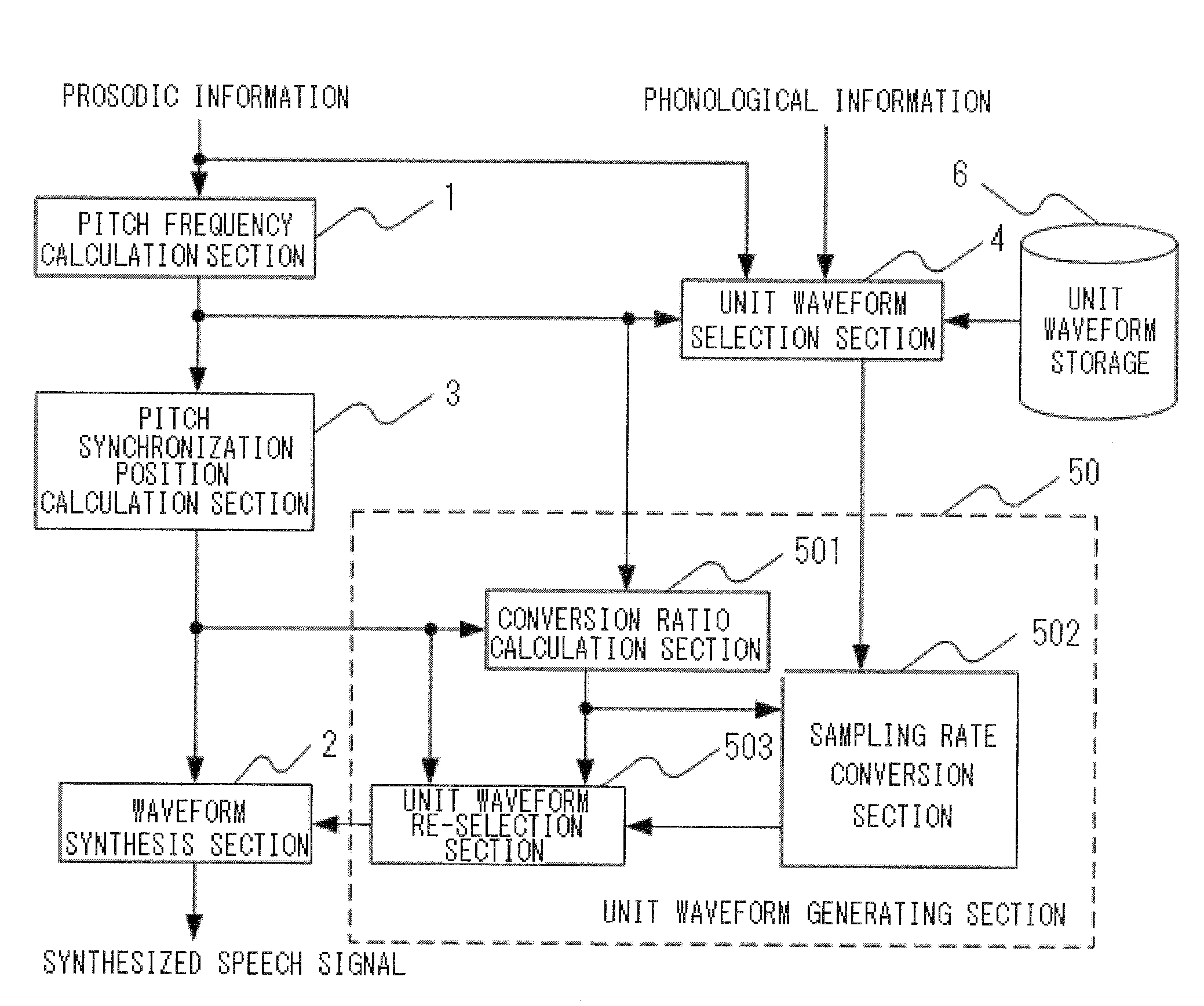
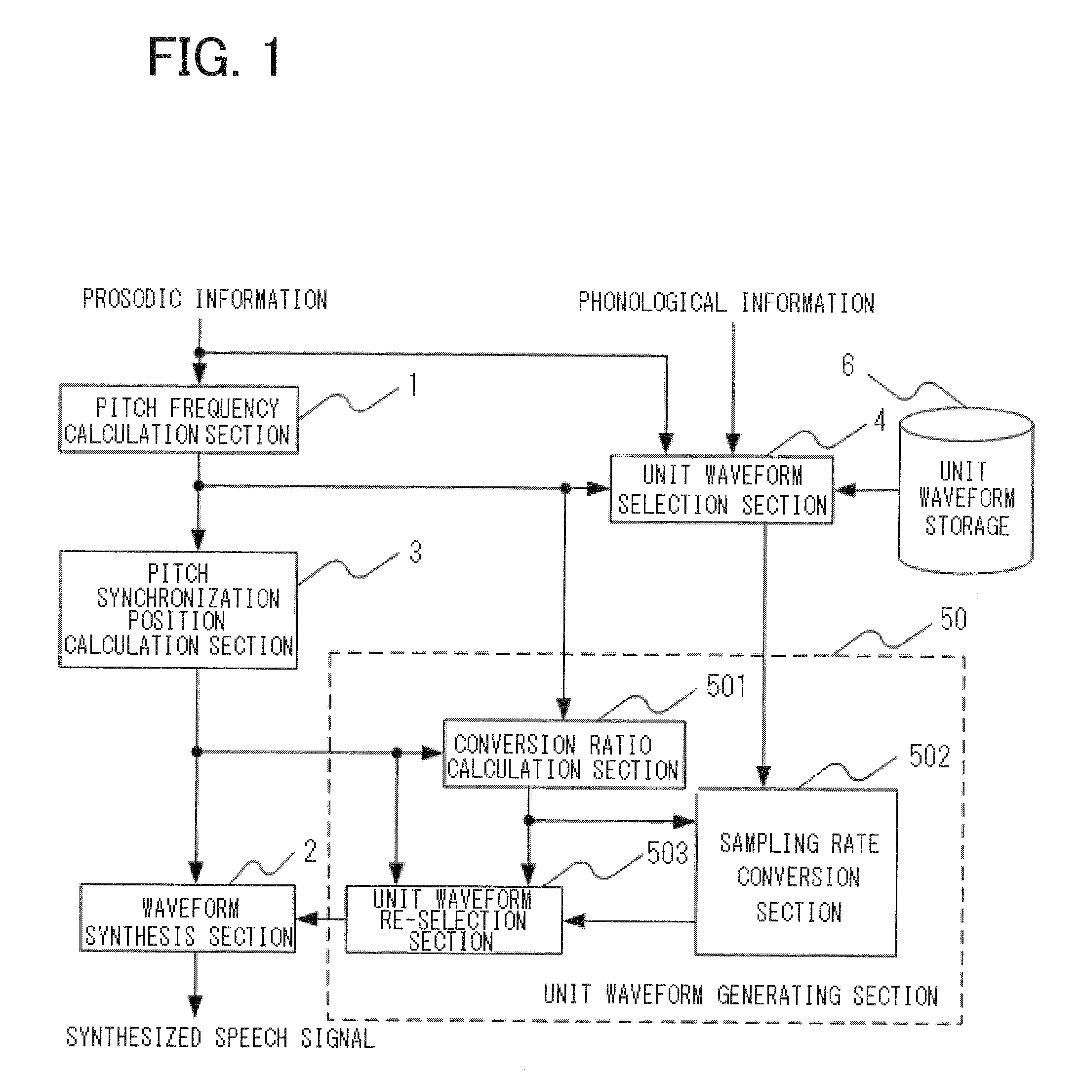
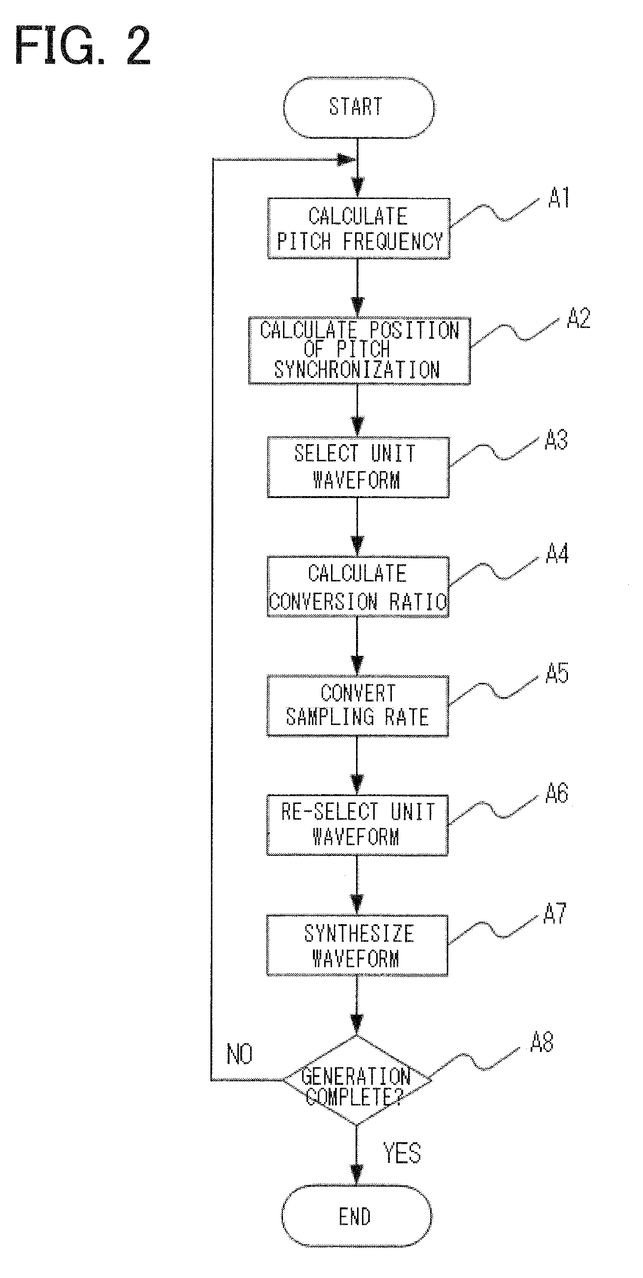
[0165]FIG. 1 shows the configuration of the first example of the present invention. FIG. 2 depicts a flowchart for illustrating the operation of the first example of the present invention.

[0166]Referring to FIG. 1, the speech synthesis apparatus according to the first example of the present invention includes a pitch frequency calculation section 1, a pitch synchronization position calculation section 3, a unit waveform selection section 4, a unit waveform storage 6, a conversion ratio calculation section 501, a sampling rate conversion section 502, a unit waveform re-selection section 503 and a waveform synthesis section 2.

[0167]The pitch frequency calculation section 1 calculates the pitch frequency from the prosodic information and delivers it to the pitch synchronization position calculation section 3 and to the unit waveform selection section 4 (step A1 of FIG. 2).

[0168]The pitch synchronization position calculation section 3 calculates the position of pitch synchronization, ba...

second embodiment

[0209]FIG. 3 is a block diagram showing the configuration of the second example of the present invention. Referring to FIG. 3, the second example of the present invention includes, as compared to the first example of FIG. 1, a compressed unit waveform storage generation section 91, compressed unit waveform storages 621, 622, . . . , 62k, and a unit waveform storage selection section 7.

[0210]Referring to FIG. 3, showing the present example, the unit waveform storage selection section 7 is provided in place of the unit waveform selection section 4 of FIG. 1, whilst a compressed unit waveform selection section 8 and a unit waveform decompression section 51 are provided in place of the conversion ratio calculation section 501, sampling rate conversion section 502 and the unit waveform re-selection section 503 of FIG. 1. The detailed operation is now described, mainly on these points of differences.

[0211]The unit waveform storage selection section 7 selects one of the compressed unit wav...

third embodiment

[0258]FIG. 8 depicts a diagram showing the configuration of the third example of the present invention. Referring to FIG. 8, showing the third example of the present invention, the unit waveform storage 6 and the compressed unit waveform storage generation section 91 of FIG. 3 are replaced by a compressed unit waveform storage generation section 92. That is, the manner of generating the compressed unit waveform storages differs from that of the above-described second example. The other elements are the same as those of the second example. The configuration and the operation of the compressed unit waveform storage generation section 92 of the third example of the present invention will now be described in detail. FIG. 9 depicts the configuration of the compressed unit waveform storage generation section 92 of FIG. 8, and FIG. 10 depicts a flowchart showing the operation of the third example of the present invention.

[0259]Referring to FIG. 9, the compressed unit waveform storage gener...


PUM


Abstract

Apparatus and method for generating high quality synthesized speech having smooth waveform concatenation. The apparatus includes a pitch frequency calculation section, a pitch synchronization position calculation section, a unit waveform storage, a unit waveform selection section, a unit waveform generation section, and a waveform synthesis section. The unit waveform generation section includes a conversion ratio calculation section, a sampling rate conversion section, and a unit waveform re-selection section. The conversion ratio calculation section calculates a sampling rate conversion ratio from the pitch information and the position of pitch synchronization, and the sampling rate conversion section converts the sampling rate of the unit waveform, delivered as input, based on the sampling rate conversion ratio. The unit waveform re-selection section selects, from the sampling-rate-converted unit waveform, the unit waveform having a phase necessary to obtain a synthesized speech waveform which will exhibit smooth waveform concatenation.

Description

TECHNICAL FIELD[0001]This invention relates to a speech synthesis technique. More particularly, this invention relates to a method, an apparatus and a program for synthesizing the speech from a text.BACKGROUND ART[0002]A variety of speech synthesis apparatus have been developed which analyze a text sentence and generate synthesized speech by synthesis by rule from the speech information indicated by the sentence.[0003]Among these, typical conventional apparatus for speech synthesis, employing the synthesis by rule, includes a storage in which are stored in large amount,[0004]unit waveforms (unit waveforms of durations of the order of a syllable or pitch extracted from natural speech, for instance);[0005]phonological information such as information on an environment in which a phoneme is uttered, or on pitch shape in the phoneme, amplitude or duration; and[0006]prosodic information.[0007]At the time of speech synthesis, a conventional speech synthesis apparatus, employing the synthes...

Claims


Application Information

Patent Timeline
Patent Type & Authority Applications(United States)
IPC IPC(8): G10L13/06G10L13/00G10L13/07G10L13/10G10L21/045
CPCG10L25/90G10L13/07
Inventor KATO, MASANORITSUKADA, SATOSHI
Owner NEC CORP
Learn More