Method for cleaning the filters of a vacuum cleaner and vacuum cleaner for carrying out the method

Active Publication Date: 2009-08-20
ALFRED KARCHER GMBH & CO KG
View PDF42 Cites 19 Cited by
  • Summary
  • Abstract
  • Description
  • Claims
  • Application Information

AI Technical Summary

Benefits of technology

[0040]In the case of a preferred embodiment, the at least one filter is adapted to be acted upon with external air by means of the closing valve for less than 200 milliseconds, in particular for less than 100 milliseconds. Being acted upon in this way means that there is no noticeable interruption in suction operation for the user, but it results in effective cleaning of the filter.
[0041]The at least one filter can preferably be impinged upon by external air by means of the at least one closing valve while maintaining a negative pressure in the region of the opening of a suction hose opening

Problems solved by technology

However, this requires careful coordination of the opening mov

Method used


Image

  • Method for cleaning the filters of a vacuum cleaner and vacuum cleaner for carrying out the method
  • Method for cleaning the filters of a vacuum cleaner and vacuum cleaner for carrying out the method
  • Method for cleaning the filters of a vacuum cleaner and vacuum cleaner for carrying out the method

Examples


Embodiment Construction

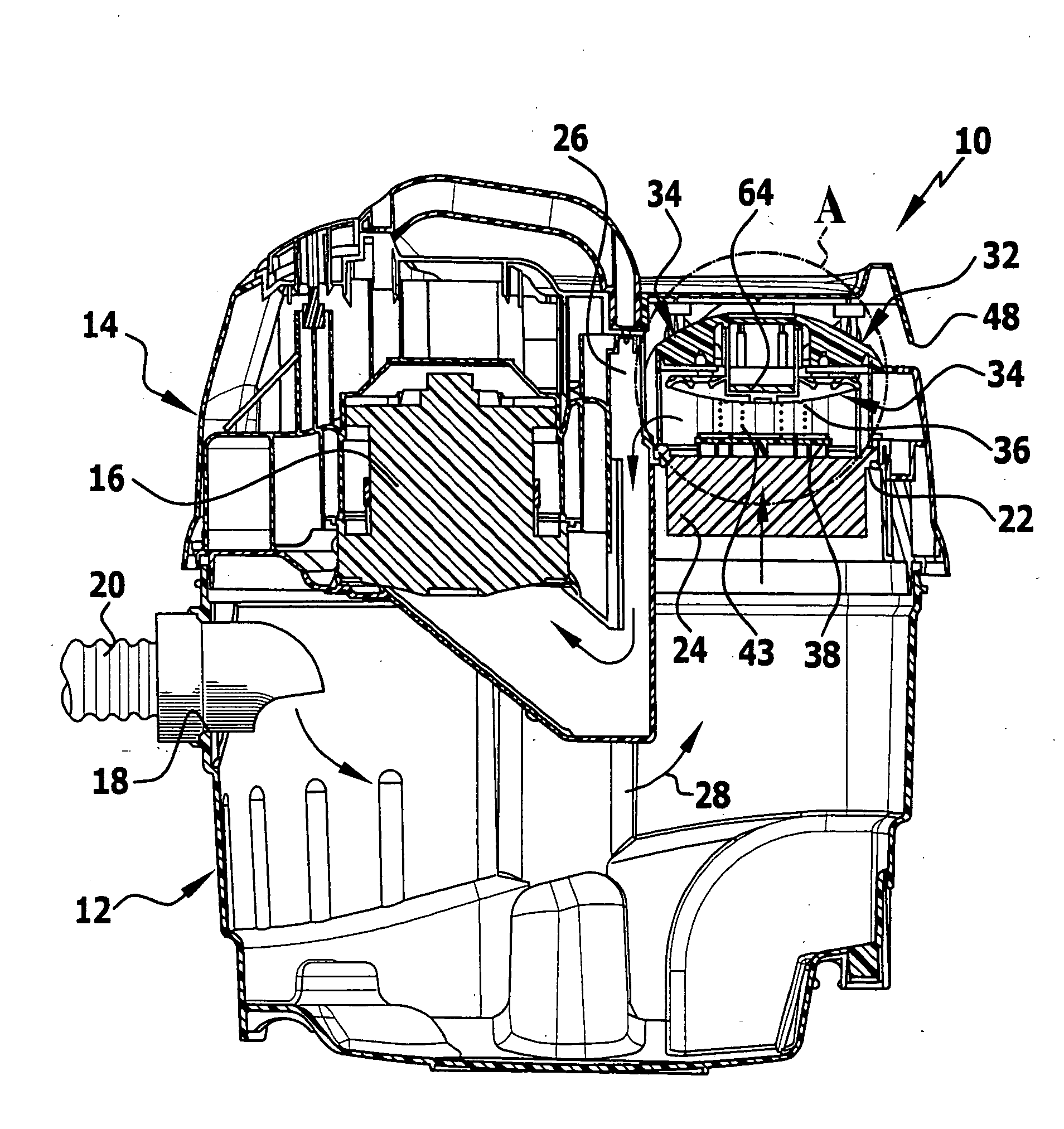
[0045]Schematically represented in the drawing is a vacuum cleaner 10, with a lower part, which forms a dirt collecting container 12, mounted on which is an upper part 14, which accommodates a suction unit 16. The dirt collecting container 12 comprises a suction inlet 18, to which a suction hose 20 can be connected. At the free end of the suction hose 20 (not represented in the drawing to achieve a better overview), a suction nozzle may be connected. Alternatively, it may be provided that the suction hose 20 is connected to a working tool, for example a drilling unit or a milling unit, so that dust produced during the operation of the working tool can be sucked away.

[0046]The upper part 14 forms a suction outlet 22 for the dirt collecting container 12. Held on the suction outlet 22 is a folded filter 24, which is followed by a suction extraction line in the form of a suction channel 26. By way of the suction channel 26, the folded filter 24 is flow-connected to the suction unit 16. ...


PUM

PropertyMeasurementUnit
Timeaaaaaaaaaa
Timeaaaaaaaaaa
Timeaaaaaaaaaa

Abstract

The invention relates to a method for cleaning the filters of a vacuum cleaner comprising a dirt collecting container, which has a suction inlet and is in flow connection with at least one suction unit via at least one filter and at least one suction extraction line, and comprising at least one external air inlet which opens into the suction extraction line downstream of the filter and can be closed by a closing valve, wherein the closing valve has a movable valve body which is acted upon by a closing spring with a closing force, which valve body lies against a valve seat in a closed position and is at a distance from the valve seat in an open position, wherein, in order to clean the filter, at least one closing valve is opened and the side of the filter that is oriented away from the dirt collecting container is impinged upon by external air. To develop the method in such a way that all the filters present can be flowed through by suction air during suction operation, but for the user there does not have to be any noticeable interruption in suction operation for filter cleaning, it is proposed according to the invention that the valve body is acted upon, irrespective of its position, by the closing force of the closing spring and, in a position at a distance from the valve seat, additionally acted upon by the repulsion force of a resilient stop element.

Description

[0001]This application is a continuation of international application number PCT / EP2006 / 007545 filed on Jul. 29, 2006.[0002]The present disclosure relates to the subject matter disclosed in international application number PCT / EP2006 / 007545 of Jul. 29, 2006, which is incorporated herein by reference in its entirety and for all purposes.BACKGROUND OF THE INVENTION[0003]The invention relates to a method for cleaning the filters of a vacuum cleaner comprising a dirt collecting container, which has a suction inlet and is in flow connection with at least one suction unit via at least one filter and at least one suction extraction line, and comprising at least one external air inlet which opens into the suction extraction line downstream of the at least one filter and can be closed by means of at least one closing valve, wherein the at least one closing valve has a valve body which is movable back and forth between a closed position and an open position, and is acted upon by a closing spr...

Claims


Application Information

Patent Timeline
IPC IPC(8): B01D46/42A47L9/20
CPCA47L9/20B01D46/521Y10S55/03F16K31/404B01D2273/28
Inventor ECKSTEIN, DANIELLANGEN, THORSTEN
Owner ALFRED KARCHER GMBH & CO KG
Why Eureka
Try Eureka