Oil passage forming member fitted with hydraulic pressure sensor

a technology of hydraulic pressure sensor and which is applied in the direction of pressure lubrication safety devices, machines/engines, cycle equipment, etc., can solve the problems of increasing the cost of oil passage forming member and increasing the cost, and achieve the effect of enhancing the accuracy of hydraulic pressure condition detection at a supplied part and reducing the cost of oil

Inactive Publication Date: 2009-08-20
HONDA MOTOR CO LTD
View PDF2 Cites 5 Cited by
  • Summary
  • Abstract
  • Description
  • Claims
  • Application Information

AI Technical Summary

Benefits of technology

[0009]According to an embodiment of the present invention, the accuracy in the detection of the hydraulic pressure condition at a supplied part is enhanced, while contriving a reduction in the cost of an oil passage forming member having an oil passage for conducting oil to the supplied part and being fitted with a hydraulic pressure sensor for detecting the hydraulic pressure in the oil passage.

Problems solved by technology

However, the formation of such a mounting hole needs special machining and, accordingly, leads to an increase in the cost of the oil passage forming member.
In addition, the plug used to close the aperture end part of the oil passage would itself increase the number of component parts, and needs a plug mounting step, thereby also causing an increase in cost.

Method used


Image

  • Oil passage forming member fitted with hydraulic pressure sensor
  • Oil passage forming member fitted with hydraulic pressure sensor
  • Oil passage forming member fitted with hydraulic pressure sensor

Examples


Embodiment Construction

[0028]Now, an embodiment of the present invention will be described below, referring to FIGS. 1 to 4.

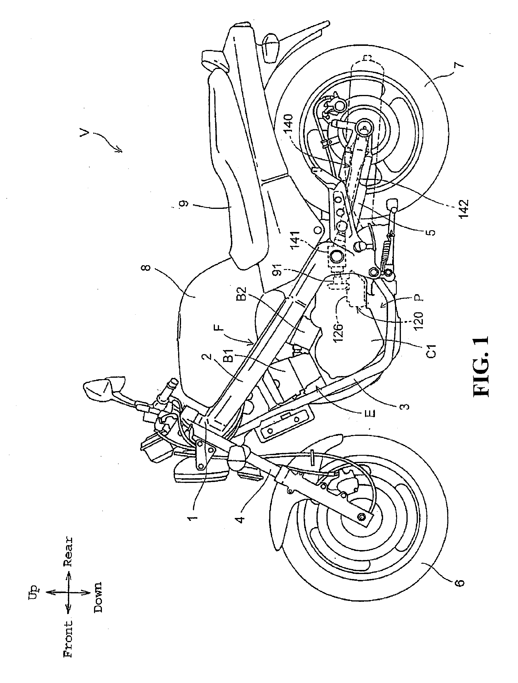
[0029]Referring to FIG. 1, in this embodiment, an oil passage forming member to which the present invention is applied is provided in a power unit P, and the power unit P is provided in a motorcycle V serving as a vehicle.

[0030]In addition, in this embodiment, the left-right direction and the front-rear direction coincide with the left-right direction and the front-rear direction with respect to the motorcycle V on which the power unit P is mounted, and the up-down direction is the vertical direction.

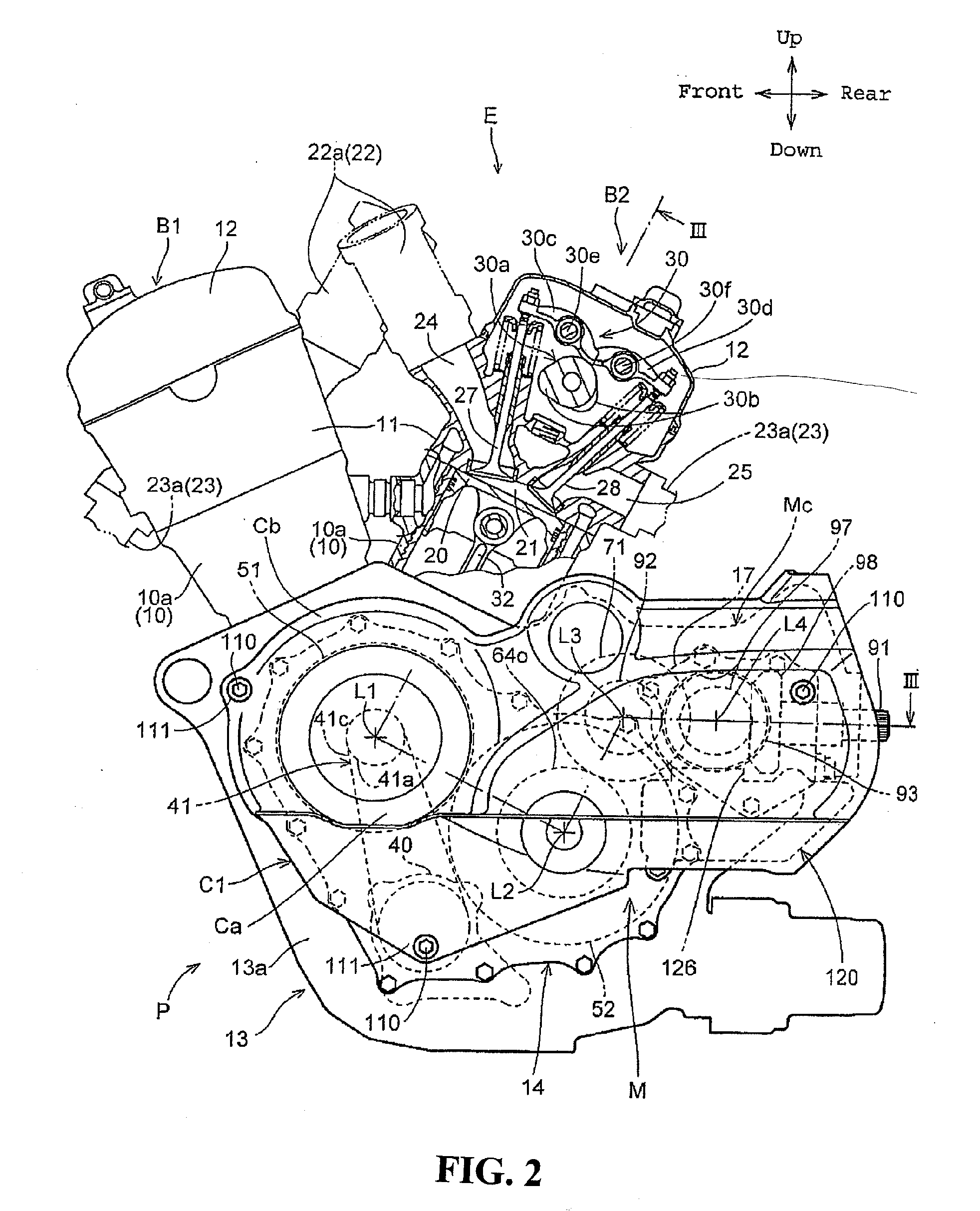
[0031]The axial direction, which term will be used in relation to each rotary shaft to be described later, means the direction of the axis of rotation of the shaft. The axial direction of a crankshaft 33 (see FIG. 3) provided in an internal combustion engine E coincides with the left-right direction in this embodiment. In addition, when either one of the rightward sense and the leftward ...


PUM


Abstract

Detecting a hydraulic pressure condition at a supplied part while reducing the cost of an oil passage forming member provided with an oil passage for conducting oil to the supplied part. In a right cover which is provided with a bent oil passage for conducting oil to a hydraulic type running clutch and which is fitted with the hydraulic pressure sensor, the oil passage is composed of a first hole and a second hole intersecting the first hole so as to constitute a bent passage part. The second hole, which is one of the first hole and the second hole, has an aperture end part with the aperture end part being closed with the hydraulic pressure sensor. The bent passage part is a bent passage part, located at a position nearest to a hydraulic pressure chamber of the running clutch, of the oil passage.

Description

CROSS-REFERENCE TO RELATED APPLICATIONS[0001]The present application claims priority under 35 USC 119 to Japanese Patent Application No. 2008-039403 filed on Feb. 20, 2008 the entire contents of which are hereby incorporated by reference.FIELD OF THE INVENTION[0002]The present invention relates to an oil passage forming member having an oil passage formed for conducting oil to a supplied part supplied with the oil, and a hydraulic oil sensor mounted for detecting the hydraulic pressure in the oil passage. The oil passage forming member is provided, for example, in a power unit including an internal combustion engine.DESCRIPTION OF BACKGROUND ART[0003]In a power unit in which an internal combustion engine and a transmission are united with each other, a multiplicity of oil passages are formed to conduct oil to supplied parts supplied with the oil, such as lubricated parts, e.g., sliding parts in the power unit, and a hydraulic operating device using the oil as a working fluid. In the...

Claims


Application Information

Patent Timeline
Patent Type & Authority Applications(United States)
IPC IPC(8): F16L55/00
CPCB62J31/00F02B61/02F01M1/20
Inventor NAKATSUKA, MASAHIKOCHO, MASAKI
Owner HONDA MOTOR CO LTD
Why Eureka
Try Eureka