Al technical title is built by PatSnap Al team. It summarizes the technical point description of the patent document.
a circulation system and wellbore technology, applied in the direction of drilling pipes, drilling holes/well accessories, sealing/packing, etc., can solve the problems of increasing the probability of undesirable “kicks”, increasing the cost of the overall drilling operation, and similar problems with the circulation of fluids
Active Publication Date: 2009-08-20
NAT OILWELL VARCO LP
View PDF32 Cites 29 Cited by
Summary
Abstract
Description
Claims
Application Information
AI Technical Summary
This helps you quickly interpret patents by identifying the three key elements:
Problems solved by technology
Method used
Benefits of technology
[0024]What follows are some of, but not all, the objects of this invention. In addition to the specific objects stated below for at least certain preferred embodiments of the invention, other objects and purposes will be readily apparent to one of skill in this art who has the benefit of this invention's teachings and disclosures. It is, therefore, an object of at least certain preferred embodiments of the present invention to provide the embodiments and aspects listed above and:
[0025]New, useful, unique, efficient, non-obvious continuous circulation systems and methods of thei
Problems solved by technology
Resulting delays in the overall drilling operation are expensive.
Often when tripping a drill string into or out of a well, the lack of continuous circulation of a drilling fluid can cause pressure changes in the well which increase the probability of undesirable “kicks”.
The connection of section
Method used
Image
Click on the blue label to locate the original text in one second.
Reading with bidirectional positioning of images and text.
Examples
Embodiment Construction
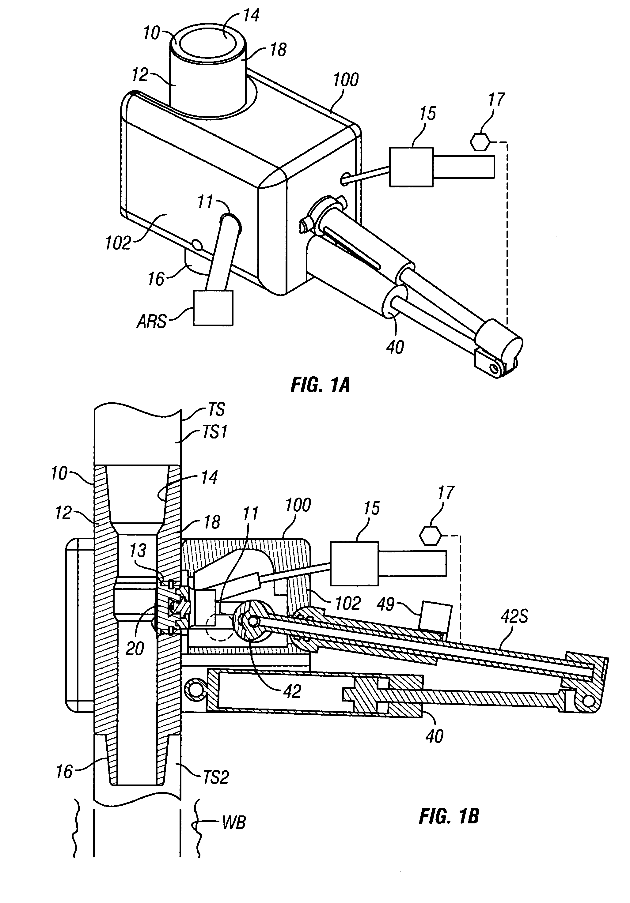
[0060]FIGS. 1A and 1B show a continuous circulation sub 10 according to the present invention and a continuous circulation system 100 according to the present invention. The continuous circulation sub 10 has a body 12 with a flow bore 14 from top to bottom, a threaded pin end 16, and a threaded box end 18. The continuous circulation sub 10 is in a tubular string TS (parts TS1 and TS2 shown schematically, FIG. 1B; e.g. a string from a rig or platform extending down into the earth). The continuous circulation system 100 has a housing 102.
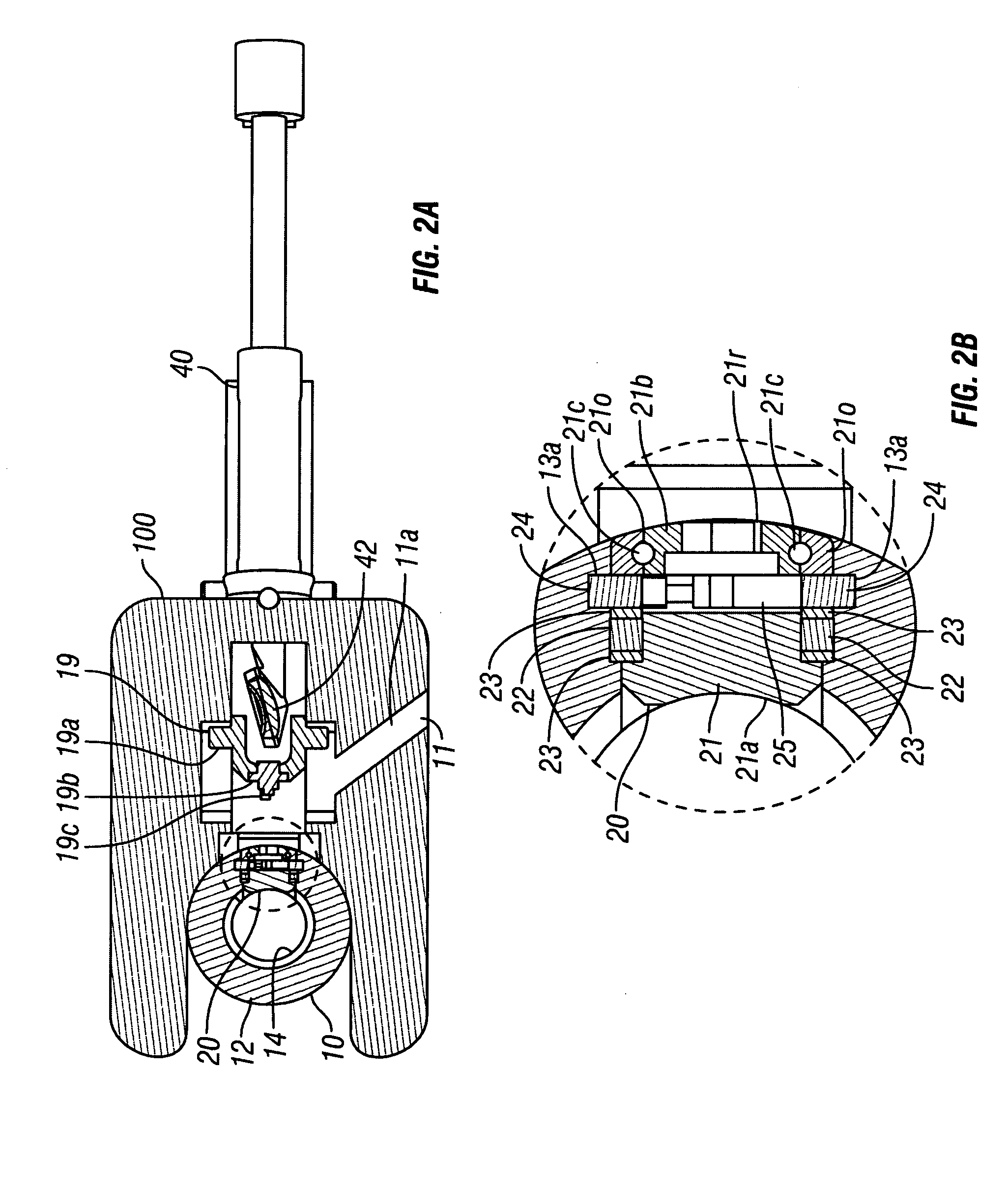
[0061]A plug apparatus 20 is removably secured in an opening 13 of the body 12. When secured in place, the plug apparatus 20 prevents fluid flow through the opening 13 (e.g. see FIGS. 1B, 2B, 3B). A plug movement device 15 (shown schematically, FIGS. 1A, 1B) selectively activates and moves the plug apparatus 20. A control system 17 controls the plug apparatus 20 and a closure apparatus 40 (described below). The control system 17, in certain aspects, i...
PUM
Abstract
Systems and methods for continuously circulating fluid, e.g., drilling mud, through a wellbore tubular string, the systems in certain aspects including a sub positionable in fluid communication with the tubular string, the sub with a body, a plug releasably closing off a side opening of the body, and a closure apparatus for selectively closing off flow from the top of the sub into and through the body, while flow is permitted below the closure apparatus through the side opening down through the body into the tubular string; and, in certain aspects, such systems and methods including tubular manipulation apparatus, e.g. an iron roughneck and working with wellbore tubulars with the tubular manipulation apparatus. This abstract is provided to comply with the rules requiring an abstract which will allow a searcher or other reader to quickly ascertain the subject matter of the technical disclosure and is submitted with the understanding that it will not be used to interpret or limit the scope or meaning of the claims, 37 CFR 1.72(b).
Description
CROSS-REFERENCE TO RELATED INVENTION[0001]The present invention and application claim the benefits of priority, under the Patent Laws, of U.S. Application Ser. No. 61 / 011,849 filed Jan. 22, 2008.BACKGROUND OF THE INVENTION[0002]1. Field of the Invention[0003]This invention is directed to wellbore operations with strings of tubulars and, in certain particular aspects, to tubular subs and related systems useful for maintaining continuous circulation during joint make-up and break-out.[0004]2. Description of Related Art[0005]There are a variety of known continuous circulation systems; for example, and not by way of limitation, the following U.S. Pat. Nos. and application present exemplary systems and components thereof: 7,350,587; 7,107,875; 6,412,554; 6,315,051; 6,591,916; 3,298,385; 1,491,986; and U.S. application Ser. No. 11 / 449,662 filed Jun. 9, 2006.[0006]These are a variety of known wellbore, subs, continuous circulation systems, and related components, including, for example, th...
Claims
Application Information
Patent Timeline
Application Date:The date an application was filed.
Publication Date:The date a patent or application was officially published.
First Publication Date:The earliest publication date of a patent with the same application number.
Issue Date:Publication date of the patent grant document.
PCT Entry Date:The Entry date of PCT National Phase.
Estimated Expiry Date:The statutory expiry date of a patent right according to the Patent Law, and it is the longest term of protection that the patent right can achieve without the termination of the patent right due to other reasons(Term extension factor has been taken into account ).
Invalid Date:Actual expiry date is based on effective date or publication date of legal transaction data of invalid patent.