Wall bracket with integrated vertical lock

a technology of vertical lock and wall bracket, which is applied in the direction of machine supports, suspension devices, furniture parts, etc., can solve problems such as display falling, and achieve the effect of preventing excessive rotation of the mounted obj

Inactive Publication Date: 2009-08-20
DAVID MIKE
View PDF23 Cites 39 Cited by
  • Summary
  • Abstract
  • Description
  • Claims
  • Application Information

AI Technical Summary

Benefits of technology

[0009]It is an object of the wall bracket with integrated vertical lock to engage the wall bracket with the back member using a motion from top downward. This is particularly important when installing a heavy item where gravity forces the item downward. The down facing slot allows an installer to start with the apparatus far above the back member and slide the bracket down the wall until the bracket makes contact with the back member where it hooks onto the back member. Gravity will the pivot and rotate the slot into engagement with the back member thereby securing the two pieces in together.
[0011]It is still another object of the wall bracket with integrated vertical lock to provide brackets that prevent excessive rotation of the mounted object. This is important because a mounted object such as a television requires some air flow for cooling and because the television should be mounted to align the television in a vertical orientation and without the rotation prevention details the television could rotate the screen to an undesirable angle.

Problems solved by technology

Without the bent ears a user could slide the monitor until one bracket becomes dislodged from the back member that would result in the display falling.

Method used


Image

  • Wall bracket with integrated vertical lock
  • Wall bracket with integrated vertical lock
  • Wall bracket with integrated vertical lock

Examples


Embodiment Construction

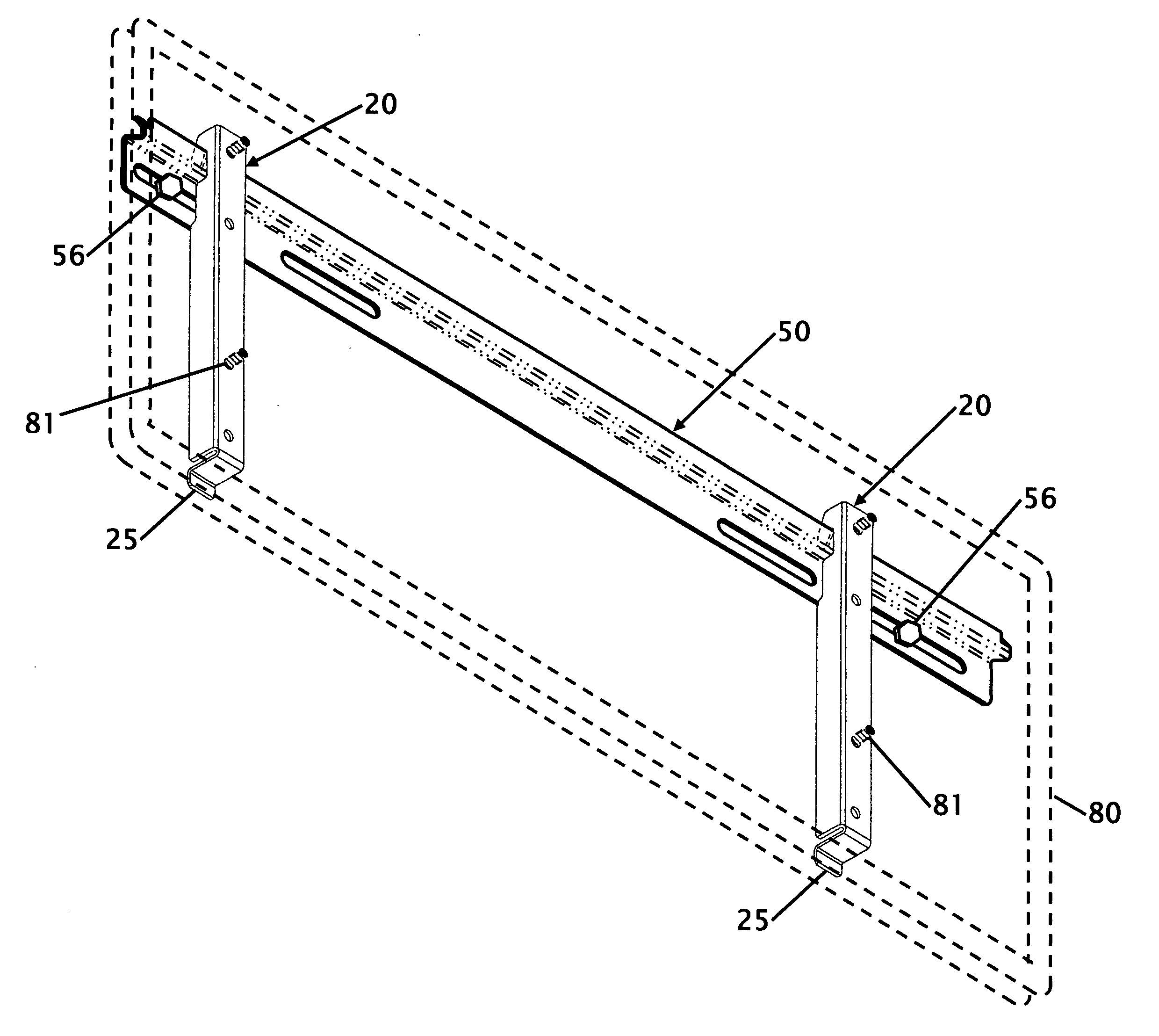
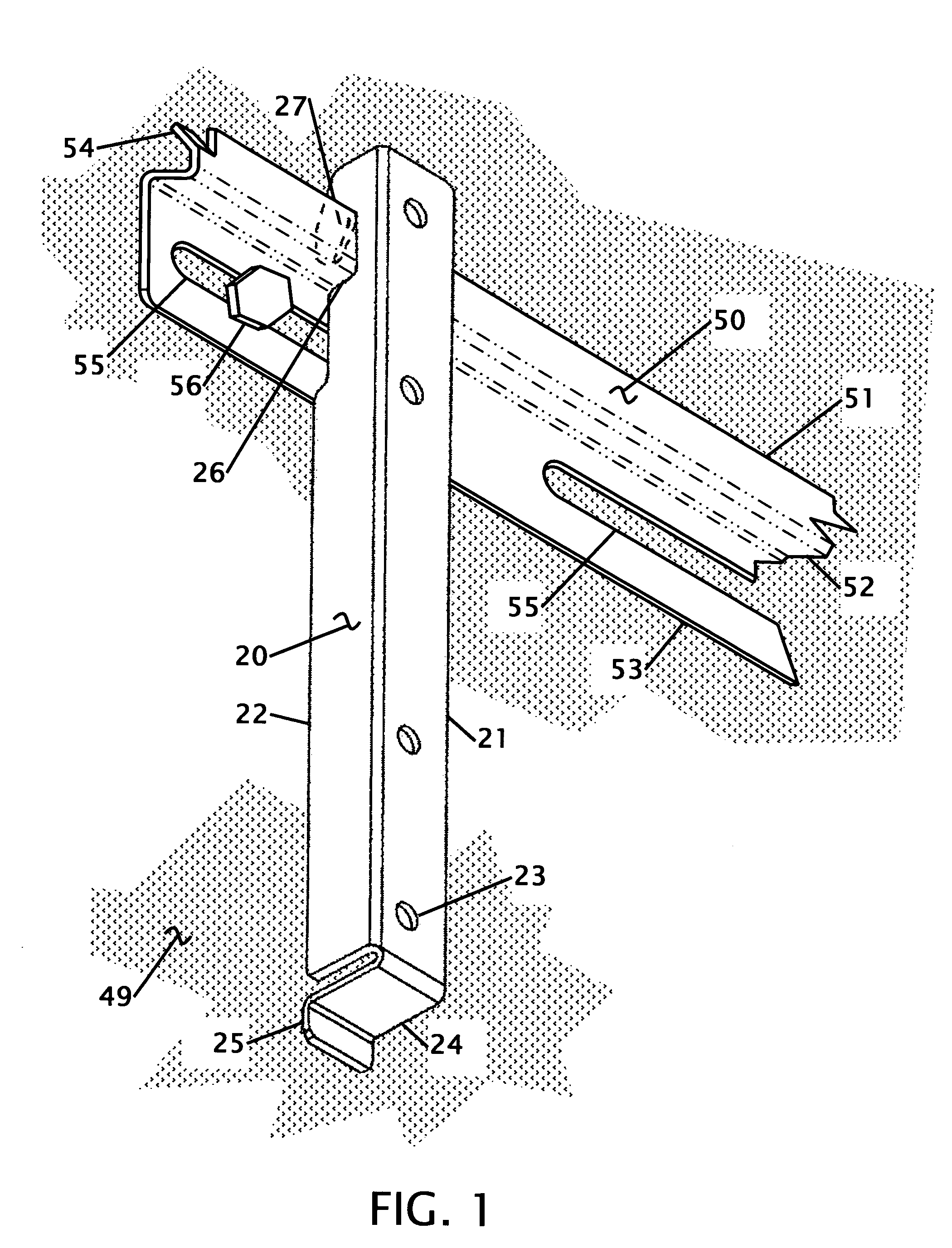
[0019]FIG. 1 shows an isometric view of the bracket 20 and back member 50 secured together and further bolted 56 to a wall. This is the configuration how the two components would be engaged when they are installed on a wall. This view provides a visual of the majority of the parts to provide a basic understanding of the design. Starting with the back member 50 that is formed from a sheet metal or equivalent material. The back member 50 is formed in an elongated shape from 12 inches or less to eight feet or more depending upon the installation. In the preferred embodiment for holding a flat panel monitor or television the back member is about 26 inches in length. This length is determined based upon the size of what is being supported. In the preferred embodiment the length allows the back member 70 to be disposed entirely behind the object being supported.

[0020]The back member has two parallel sections including a wall mounting section 53 and an upper tab 51. While these sections ar...


PUM


Abstract

Improvements in a wall mount bracket are disclosed. The bracket works with flat panel televisions, monitors, signs and boards. An elongated back member is secured to a wall. The back member has a single vertical tang. One or more brackets have an angled slot that engages onto the tang. Once engaged the bracket is rotated to a vertical orientation. In the vertical orientation a ledge on the angled slot prevents the bracket from being lifted off the back member unless the bracket is rotated to align the angled slot with the tang. The back member further has bent tabs to prevent the bracket from being slid horizontally off the back member. The entire placement and locking of the bracket and the back member is performed from a top to bottom motion.

Description

FIELD OF THE INVENTION[0001]This invention relates to improvements in a wall mountable bracket. More particularly, the present wall mountable bracket allows for placement of the bracket on a wall hanger in a top down motion. The bracket has a narrow rotational engage window where the bracket slides onto the wall hanger. Once engaged the bracket rotates into vertical orientation and locks the bracket onto the wall hanger preventing disengagement from vertical lifting of the bracket.BACKGROUND OF THE INVENTION[0002]There are many types of TV, board and shelf mounting patents that incorporate a variety of different attachment methods. Each patent approaches the problem based upon security of the device on the wall and the method of installation. To focus the background this disclosure limits the identified patents with inventions that secure to a back brace with a top to bottom securing motion and to brackets that provide some form of blocking to prevent disconnection with the back bra...

Claims


Application Information

Patent Timeline
Patent Type & Authority Applications(United States)
IPC IPC(8): A47F5/08
CPCA47B96/067F16M13/02F16M11/041
Inventor DAVID, MIKE
Owner DAVID MIKE
Why Eureka
Try Eureka