Display and detachable base assembly thereof

a technology of a base assembly and a display, which is applied in the direction of washstands, electrical apparatus casings/cabinets/drawers, lighting support devices, etc., can solve the problems of increasing transportation costs, inconvenient complex structure of the connecting element, and how complex the connecting element is, and achieves the effect of easy installation or removal from the screen

Inactive Publication Date: 2009-08-20
HANNSPREE INC
View PDF8 Cites 8 Cited by
  • Summary
  • Abstract
  • Description
  • Claims
  • Application Information

AI Technical Summary

Benefits of technology

[0008]The main objective of the invention is to provide a display having a screen and a base assembly easily installed on or detached from the screen.
[0009]The display in accordance with the present invention comprises a base, a pivot unit and a screen. The base has a hollow hole. The hollow hole is formed downwardly on the top of the base and has a top opening and at least one wedge hole. Each wedge hole is formed through and at the bottom edge of the bottom of the hollow hole. The pivot unit is mounted detachably in the hollow hole of the base and has at least one engaging element. Each engaging element is formed on the outer surface of the pivot unit and is mounted detachably through the wedge hole on the base. The screen has an indentation formed on the bottom of the screen for connecting the screen to the pivot unit. Therefore, the pivot unit can be detached conveniently from the base.

Problems solved by technology

However, how powerful function the connecting element has results in how complex structure the connecting element has.
Furthermore, a complex structure of the connecting element is inconveniently for detaching the screen and the base.
Therefore large size flat panel display results in larger size base and larger size flat panel display also increases cost for transportation because of large package size requires more transportation room.

Method used


Image

  • Display and detachable base assembly thereof
  • Display and detachable base assembly thereof
  • Display and detachable base assembly thereof

Examples


Embodiment Construction

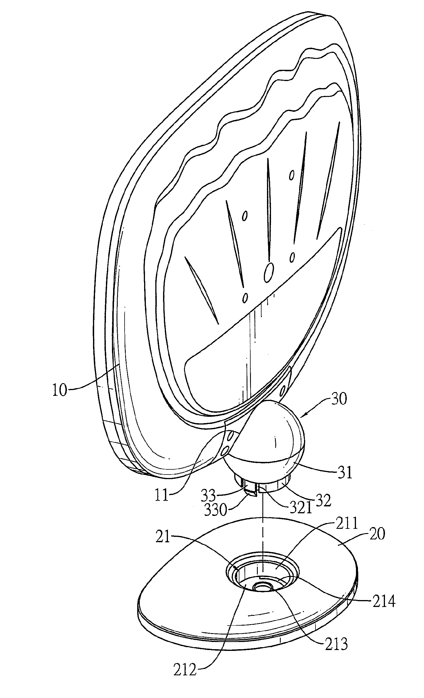
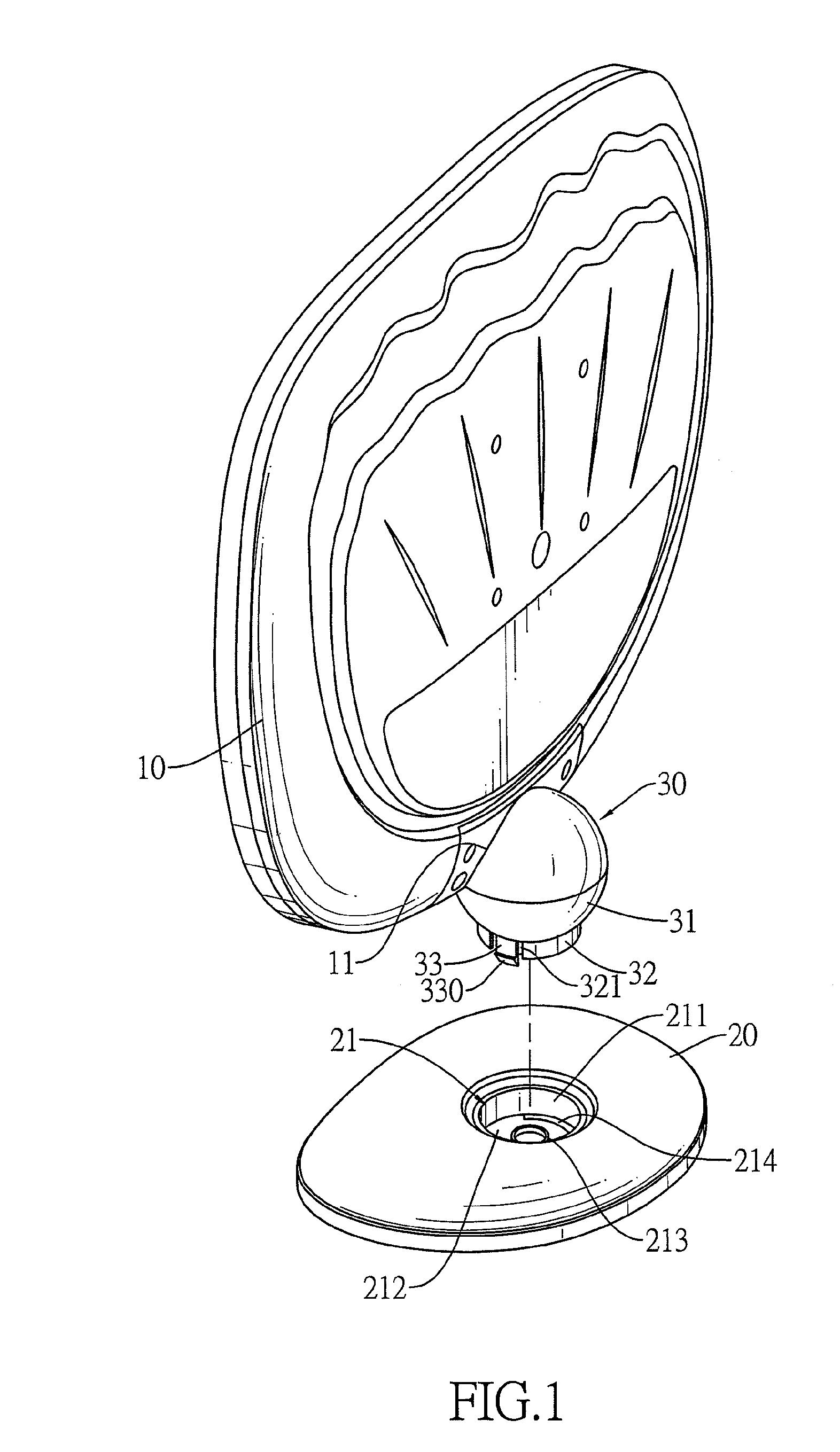
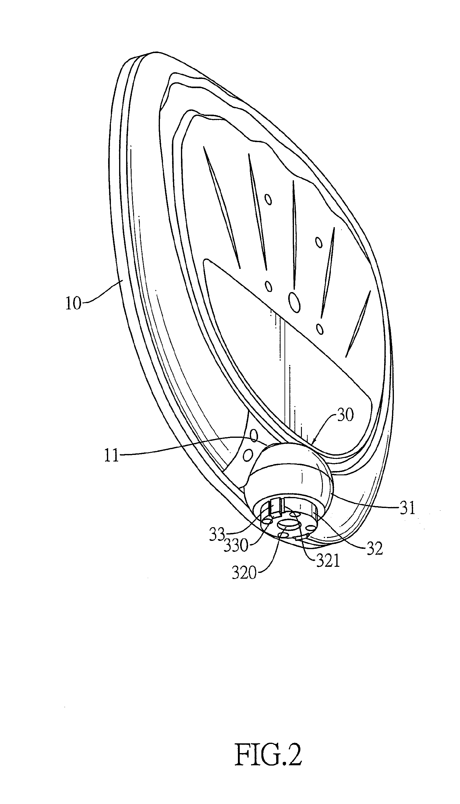
[0017]With reference to FIG. 1, a display in accordance with the present invention comprises a base assembly and a screen (10).

[0018]With further reference to FIG. 3, the base assembly comprises a base (20) and a pivot unit (30). The base (20) has a hollow hole (21) and at least one optional notch (22). The hollow hole (21) is formed downwardly on the top of the base (20) and has a top opening, an inner side wall (211), an optional second pivot (213) and at least one wedge hole (214). The bottom (212) of the hollow hole (21) is connected to the bottom end of the inner side wall (211) of the hollow hole (21) and has a bottom edge being adjacent to the inner side wall (211) of the hollow hole (21). The second pivot (213) is formed on the top surface of the bottom (212) of the hollow hole (21). Each wedge hole (214) is formed through and at the bottom edge of the bottom (212) of the hollow hole (21). Each notch (22) is formed on the bottom of the base (20), corresponds and connects to ...


PUM


Abstract

A display has a base, a pivot unit and a screen. The base has a hollow hole. The hollow hole is formed downwardly on the top of the base and has a top opening and at least one wedge hole. Each wedge hole is formed through and at the bottom edge of the bottom of the hollow hole. The pivot unit is mounted detachably in the hollow hole of the base and has at least one engaging element. Each engaging element is formed on the outer surface of the pivot unit and is mounted detachably through the wedge hole on the base. The screen has an indentation formed on the bottom of the screen for connecting the screen to the pivot unit. Therefore, the pivot unit can be detached conveniently from the base.

Description

BACKGROUND OF THE INVENTION[0001]1. Field of the Invention[0002]The present invention relates to a display and a base assembly thereof, and more particularly to a display having a screen and a base assembly easily installed on or detached from the screen.[0003]2. Description of Related Art[0004]Flat panel displays such as liquid crystal displays (LCD) and plasma display panel (PDP) displays have replaced conventional cathode ray tube (CRT) displays because flat panel displays have advantages of light weight and slim appearance. An upright type flat panel display comprises a screen, a base and a connecting element. The screen is pivotally installed on the base by the connecting element to allow a user to pivot the screen up or down or to rotate the screen on the base.[0005]However, how powerful function the connecting element has results in how complex structure the connecting element has. Furthermore, a complex structure of the connecting element is inconveniently for detaching the ...

Claims


Application Information

Patent Timeline
Patent Type & Authority Applications(United States)
IPC IPC(8): A47B91/00
CPCF16M13/00F16M11/10F16M11/16F16M11/2014F16M13/005F16M2200/08
Inventor HUANG, WEN-HUNGHSIEH, KUAN-CHENG
Owner HANNSPREE INC
Why Eureka
Try Eureka