
Device and A Method For Detection Of and Warning Against Tsunamis

a tsunami and tsunami technology, applied in the field of tsunami detection and tsunami warning devices, can solve the problems of high cost, inconvenient operation, and inability to detect tsunamis, and achieve the effect of avoiding tsunamis, avoiding tsunamis, and avoiding tsunamis

Inactive Publication Date: 2009-08-20
MELIN SIGURD
View PDF5 Cites 3 Cited by
  • Summary
  • Abstract
  • Description
  • Claims
  • Application Information

AI Technical Summary

Benefits of technology

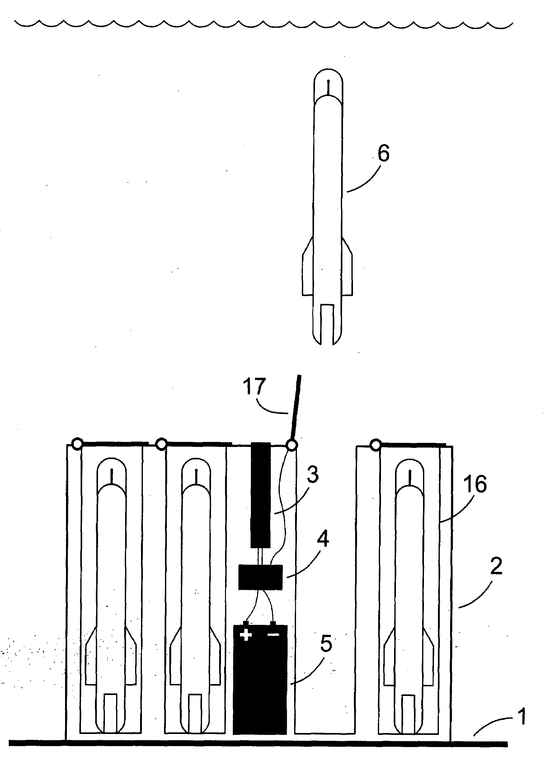
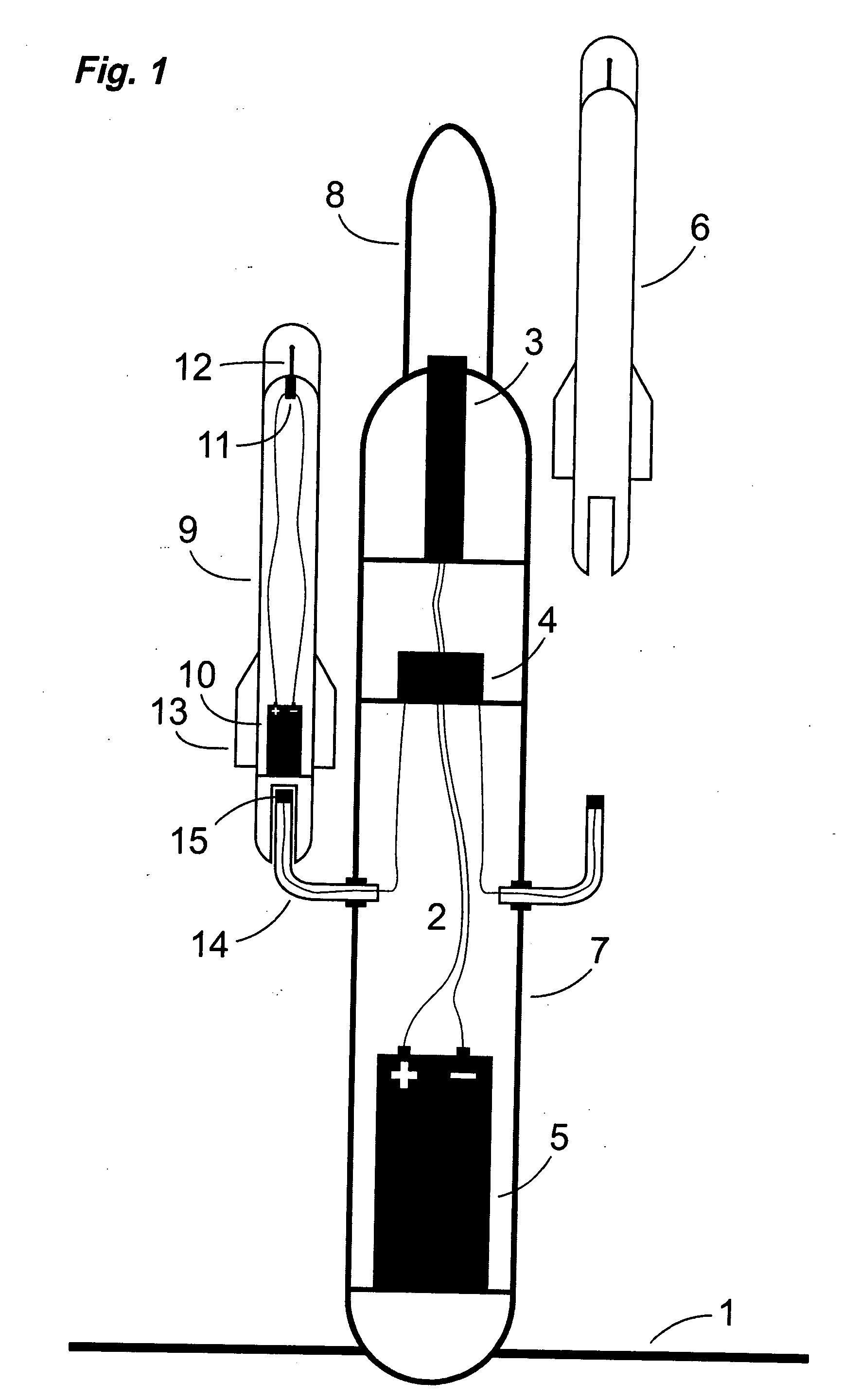
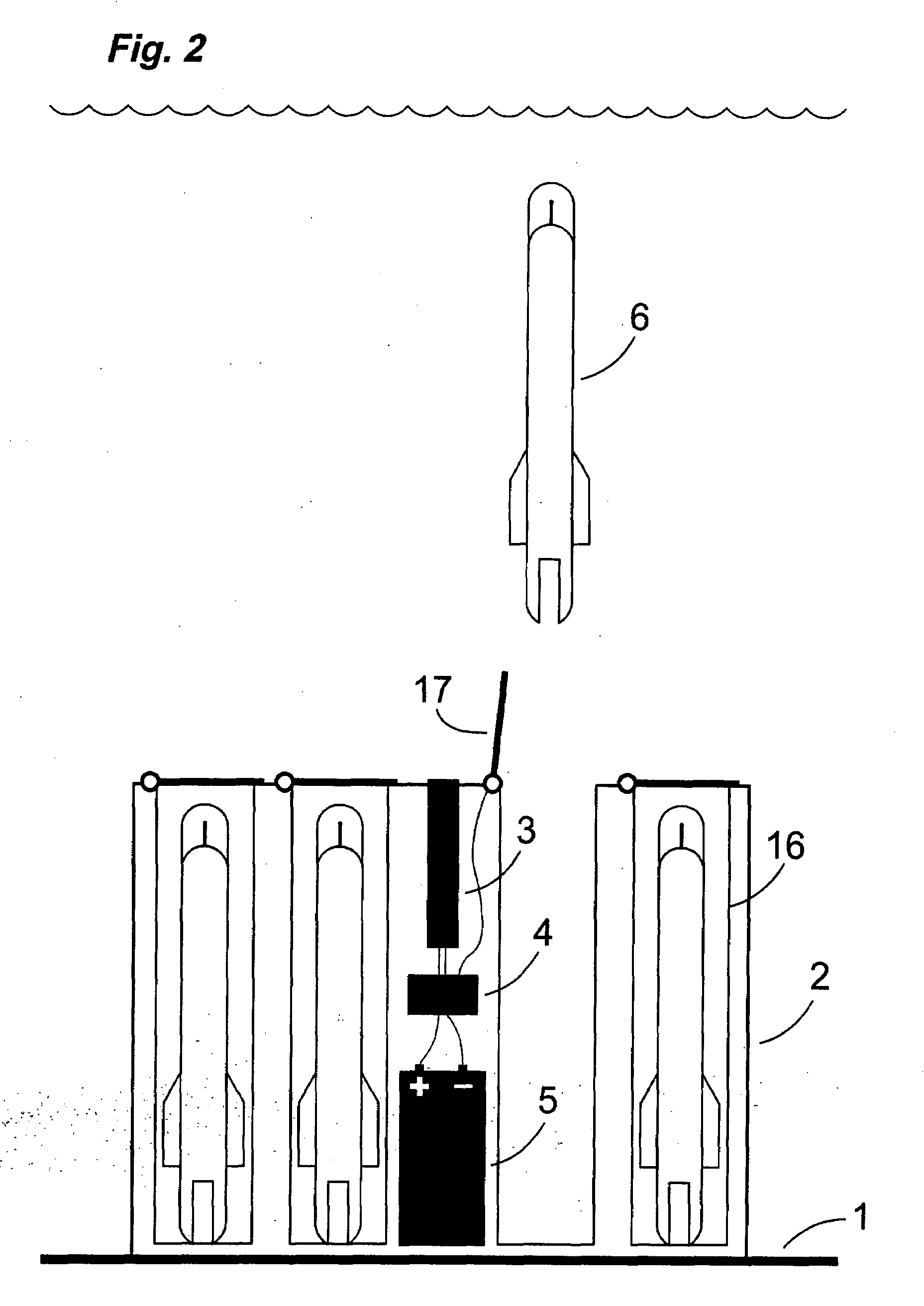
"The invention is a device that can automatically detect and warn against tsunamis on the seabed. It consists of a stationary base unit and a number of attached parts, called \"couriers,\" which can be released one by one. When a tsunami passes by, the device detects a change in water pressure caused by the wave and activates a mechanism that releases one of the couriers. The courier ascends to the surface and transmits a radio signal to a receiver on land, which in turn activates an alarm. The device is simple, cheap, and reliable, and can be used in both large scale and local tsunami warning systems. It can be left in the seabed for several days without maintenance. The couriers are shaped like torpedo-like projectiles to make the ascending time to the surface as fast as possible. The device can be tested regularly and has a mechanism to reduce the criteria for alarm to a level at which it also warns against smaller or slower pressure changes that may occur naturally."

Problems solved by technology

A tsunami that strikes a coast is a very insidious type of natural disaster, since it is hardly noticed before it approaches land.
However, during the time, which is needed to detect, analyze and warn against a tsunami, the same manage to travel a considerable distance, since its speed over the deep sea may amount to over 800 km / h.
Another problem is to get the transmitted warning out to the people that for the moment are in the danger zone quickly enough.
This makes them quit expensive.
The drawback of this device is that the same has to be taken care of after the triggered alarm, restored in an active state and once again be placed on the seabed.
Thereto, the operability may not be tested without carrying out the entire procedure.
A passing tsunami results in a characteristic change of the water pressure at the seabed.

Method used


Image

  • Device and A Method For Detection Of and Warning Against Tsunamis
  • Device and A Method For Detection Of and Warning Against Tsunamis
  • Device and A Method For Detection Of and Warning Against Tsunamis

Examples


Embodiment Construction

[0018]Ordinary ocean waves consist of the visible wave on the surface as well as a shock wave below the surface. The increase in pressure that the passing ordinary wave creates may only be registered close under the wave. At greater depths is it calm and the variations of the water pressure are small, also during a storm.

[0019]On the contrary, a tsunami is a shock wave that propagates through the entire water body, and that therefore may be registered at great depths. When the tsunami reaches shallow water the energy is concentrated, the pressure increases and a bigger wave starts to grow.

[0020]A tsunami is thereby easier and cheaper to detect at shallow water than at deeper. This may be used by locating the detectors in close connection to banks, islands and capes that protrudes from the coast. The only demand is that it is not so shallow that the pressure change from a tsunami is not separatable from the pressure change from an ordinary storm wave.

[0021]The device is located on th...


PUM


Abstract

A device for detection of and warning against tsunamis. The device is characterized in that it includes a stationary base unit (2) and at least one courier (6) disengagably connected to the base unit (2), elements (3, 4, 5) for detection of the fulfillment of a predetermined condition, and elements (15) for releasing the courier from the base unit when the condition is fulfilled, the courier (6) including elements (10, 11, 12) in order to communicate to an external receiver that it is released from the base unit (2). A method for detection of and warning against tsunamis is also disclosed.

Description

TECHNICAL FIELD OF THE INVENTION[0001]This invention relates to a device for automatic detection of and warning against tsunamis, intended to be located on the seabed, comprising a sensor, e.g. a pressure sensor, a processor, a power source as well as one or more disengagable parts, each provided with a radio transmitter and a power source of its own.BACKGROUND OF THE INVENTION AND PRIOR ART[0002]A tsunami that strikes a coast is a very insidious type of natural disaster, since it is hardly noticed before it approaches land. That was the circumstances around the wave that caused death and holocaust in the Indian Ocean in December 2004. A several meter high wave that strikes a coast, needs to be just a few decimeters high as long as it travels over the deep sea, Since the wave at the same time may have a wavelength of several kilometers, is it not detectable without instruments.[0003]Such instruments are developed. By measuring the variations of the water level, or of the water press...

Claims


Application Information

Patent Timeline
Patent Type & Authority Applications(United States)
IPC IPC(8): G08B21/10
CPCG01C13/008G01V1/008G08B21/10G01W1/00G01W1/10G01V1/38G01V1/01G01C13/002
Inventor MELIN, SIGURD
Owner MELIN SIGURD
Learn More