
Method for chemical etching of a needle cannula

a needle cannula and chemical etching technology, which is applied in the field of needle cannula chemical etching, can solve the problems of etching liquid to penetrate into and out of the interior of the needle cannula

Inactive Publication Date: 2017-11-21
NOVO NORDISK AS
View PDF28 Cites 0 Cited by
  • Summary
  • Abstract
  • Description
  • Claims
  • Application Information

AI Technical Summary

Benefits of technology

[0017]It is an object of the present invention to provide a simple, cheap and reliable method for manufacturing a needle cannula with improved flow characteristic combining a small outside diameter with a satisfactory resistance against breakage when bended.
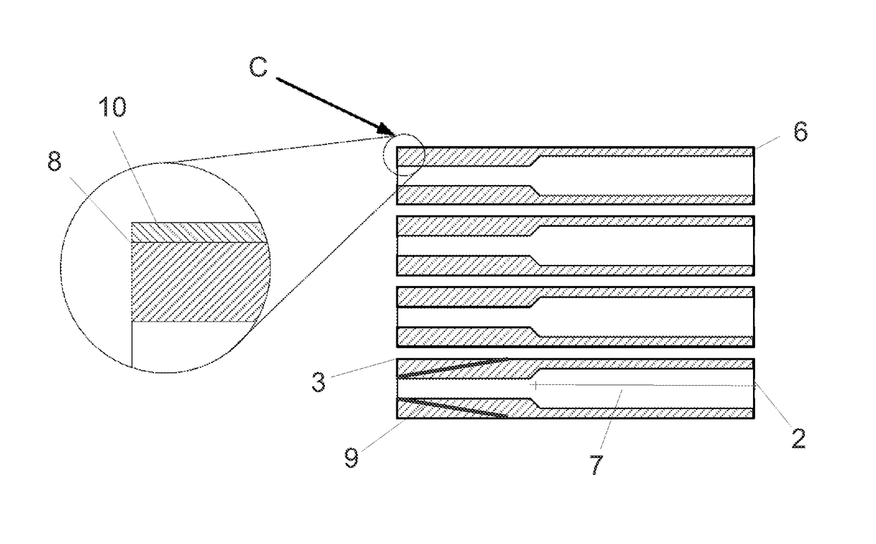
[0018]Further, it is an object to provide a method by which the interior material of a needle cannula can be chemically removed thereby increasing the flow through the needle cannula and especially a method by which material is removed from only a part of the axial length of the needle cannula thereby improving the flow through the needle cannula but maintaining the resistance against breakage.

Problems solved by technology

However, it is a problem for the etching liquid to penetrate in and out of the interior of the needle cannula due to the surface tension of the liquid bath, especially if the inside diameter is very small, which is the case for most needle cannulas today.

Method used


Image

  • Method for chemical etching of a needle cannula
  • Method for chemical etching of a needle cannula
  • Method for chemical etching of a needle cannula

Examples


example

[0067]Stainless G31 steel tubes having the following characteristic were covered on their outer surfaces with melted wax:[0068]Length: 100 mm,[0069]Outer diameter: 0.26 mm,[0070]Inner diameter: 0.15 mm,[0071]Steel type: AISI 304L[0072]Wax type: Freeman Flakes, Premium Injection Wax with a melting temperature of 60° C.

[0073]A coherent bundle of 100 waxed tubes were then formed by application of heat and force. The bundle was cut into shorter bundles having a length of 18 mm.

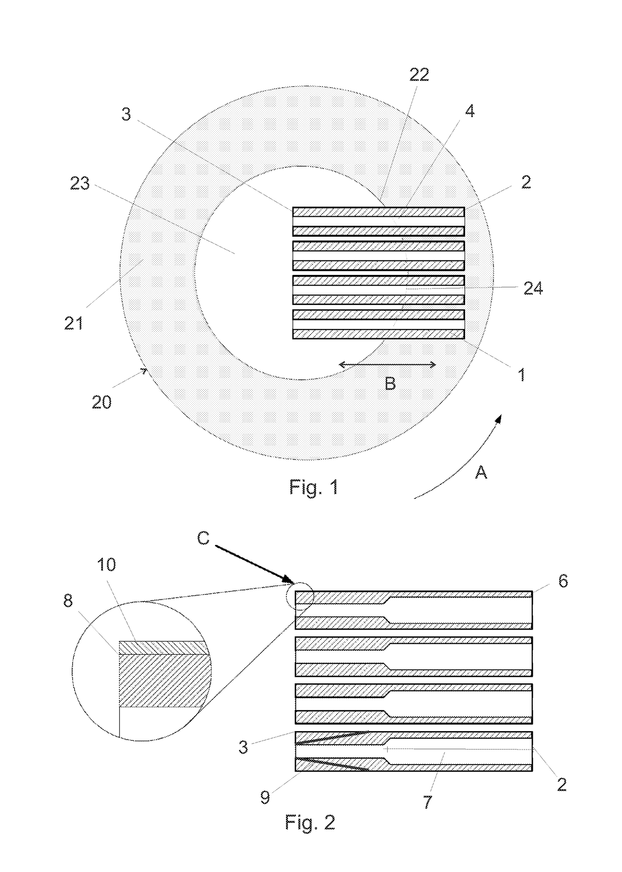
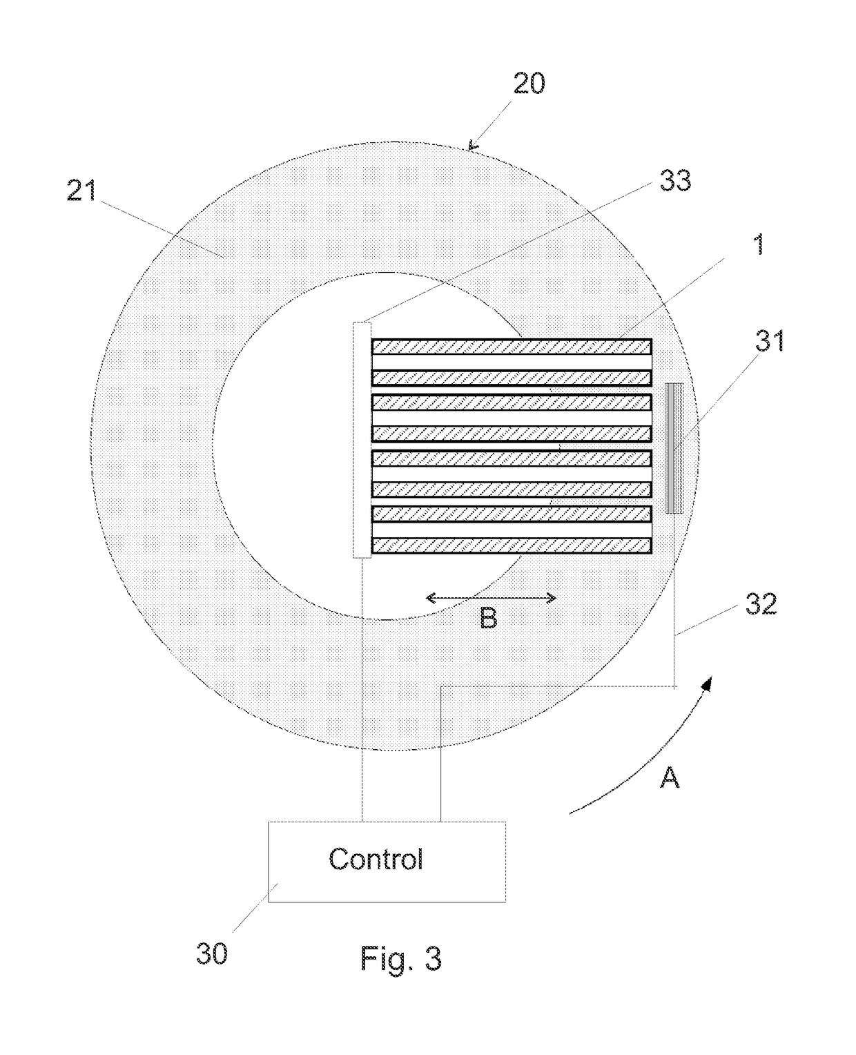
[0074]A short bundle was placed in a centrifuge and subjected to 600 RPM. This resulted in a centripetal acceleration of approximately 100 times the gravitational acceleration (100G).

[0075]The bundle was during centrifugation dipped repeatedly in an etching solution having a composition of: 10 wt % FeCl3, 10 wt % HCL and 5 wt % HNO3.

[0076]The solution was maintained at 25° C. The bundle was moved into the etching solution such that it travelled 15 mm inside the tubes during a dipping cycle.

[0077]A cycle consisted...


PUM

PropertyMeasurementUnit
diameteraaaaaaaaaa
diameteraaaaaaaaaa
lengthaaaaaaaaaa

Abstract

A regular metallic, cylindrical tubular needle cannula (1) is subjected to a metal etching liquid (21) in the inside lumen (4) thereby increasing the inside diameter and enhancing the flow properties while maintaining the outside appearance. The inside diameter is only increased over a controlled length (7) of the full length of the needle cannula (1) leaving sufficient length and wall thickness to also taper the outside diameter.

Description

CROSS-REFERENCE TO RELATED APPLICATIONS[0001]This application is a 35 U.S.C. §371 national stage application of International Patent Application PCT / EP2010 / 063787 (published as WO 2011 / 033102), filed Sep. 20, 2010, which claimed priority of European Patent Application 09170828.9, filed Sep. 21, 2009, European Patent Application 09179188.9, filed Dec. 15, 2009, and European Patent Application 10156387.2, filed Mar. 12, 2010; this application further claims priority under 35 U.S.C. §119 of U.S. Provisional Application 61 / 245,435, filed Sep. 24, 2009.THE TECHNICAL FIELD OF THE INVENTION[0002]The invention relates to a method of manufacturing a needle cannula having improved flow properties and a needle cannula manufactured according to the method. The invention also relates to a tool for carrying out the method.DESCRIPTION OF RELATED ART[0003]Needle assemblies are commonly used to either inject substances into or extract substances out of human or animal bodies. Such needle assemblies ...

Claims


Application Information

Patent Timeline
Patent Type & Authority Patents(United States)
IPC IPC(8): B44C1/22C23F1/28B21G1/08B21G1/00A61M5/32C23F1/04A61B17/20A61B17/00
CPCC23F1/04A61M5/32B21G1/006C23F1/28B21G1/08A61M2207/00A61B17/205A61B2017/00526
Inventor LARSEN, ANDRECHRISTOFFERSEN, LASSE WENGELANDERSEN, MIKAELPREUTHUN, JAN HARALD
Owner NOVO NORDISK AS
Learn More