
Connecting device of parking cable for electric parking brake

a technology of connecting device and parking cable, which is applied in the direction of coupling, rod connection, coupling device connection, etc., can solve the problems of difficult assembly work, the assembly of the parking cable cannot be connected with the motor driven parking brake in the state in which the parking brake assembly has been assembled, and the assembly of the parking cable assembly

Active Publication Date: 2009-08-20
HL MANDO CORP
View PDF24 Cites 23 Cited by
  • Summary
  • Abstract
  • Description
  • Claims
  • Application Information

AI Technical Summary

Benefits of technology

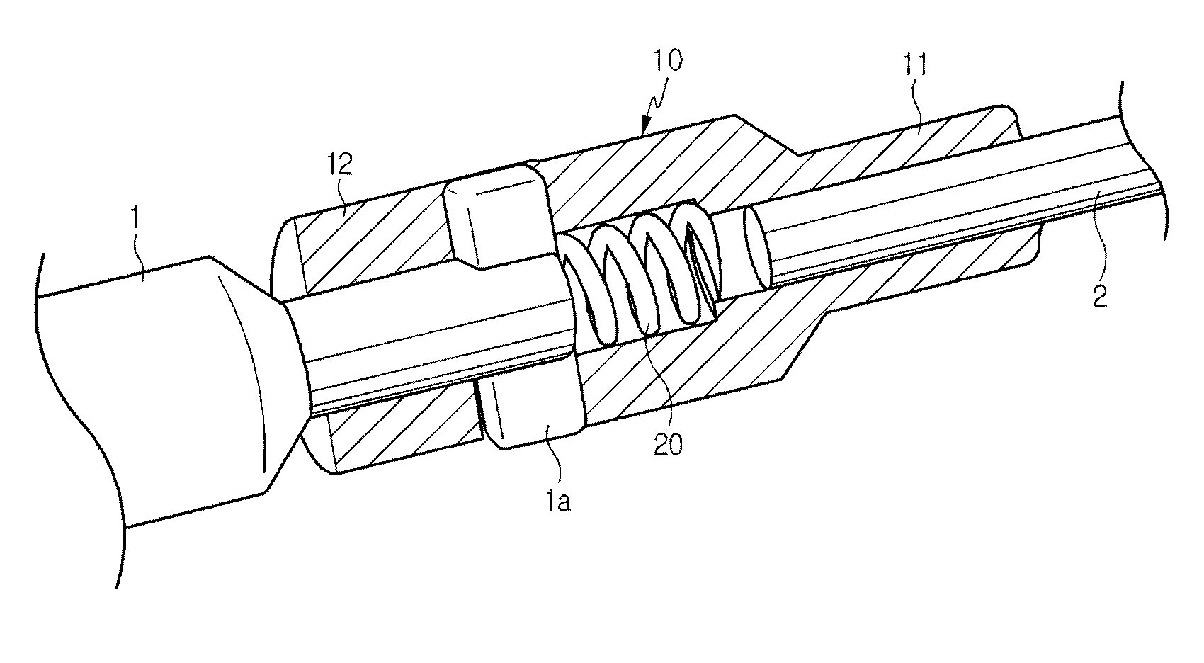
[0011]Accordingly, it is an aspect of the present invention to provide a connecting device of a parking cable for an electric brake, which can connect an actuator of an electric parking brake with a parking cable by using a connector.

Problems solved by technology

However, since a parking cable assembly is connected with the motor driven parking brake, the parking cable assembly, which is assembled separately from a parking brake assembly, cannot be connected with the motor driven parking brake in a state in which the parking brake assembly has been assembled.
In other words, since the parking cable assembly is integrally connected with an actuator such as a motor of the motor driven parking brake, assembly work may be difficult.

Method used


Image

  • Connecting device of parking cable for electric parking brake
  • Connecting device of parking cable for electric parking brake
  • Connecting device of parking cable for electric parking brake

Examples


Embodiment Construction

[0017]Hereinafter, the present invention will be described in detail with reference to accompanying drawings.

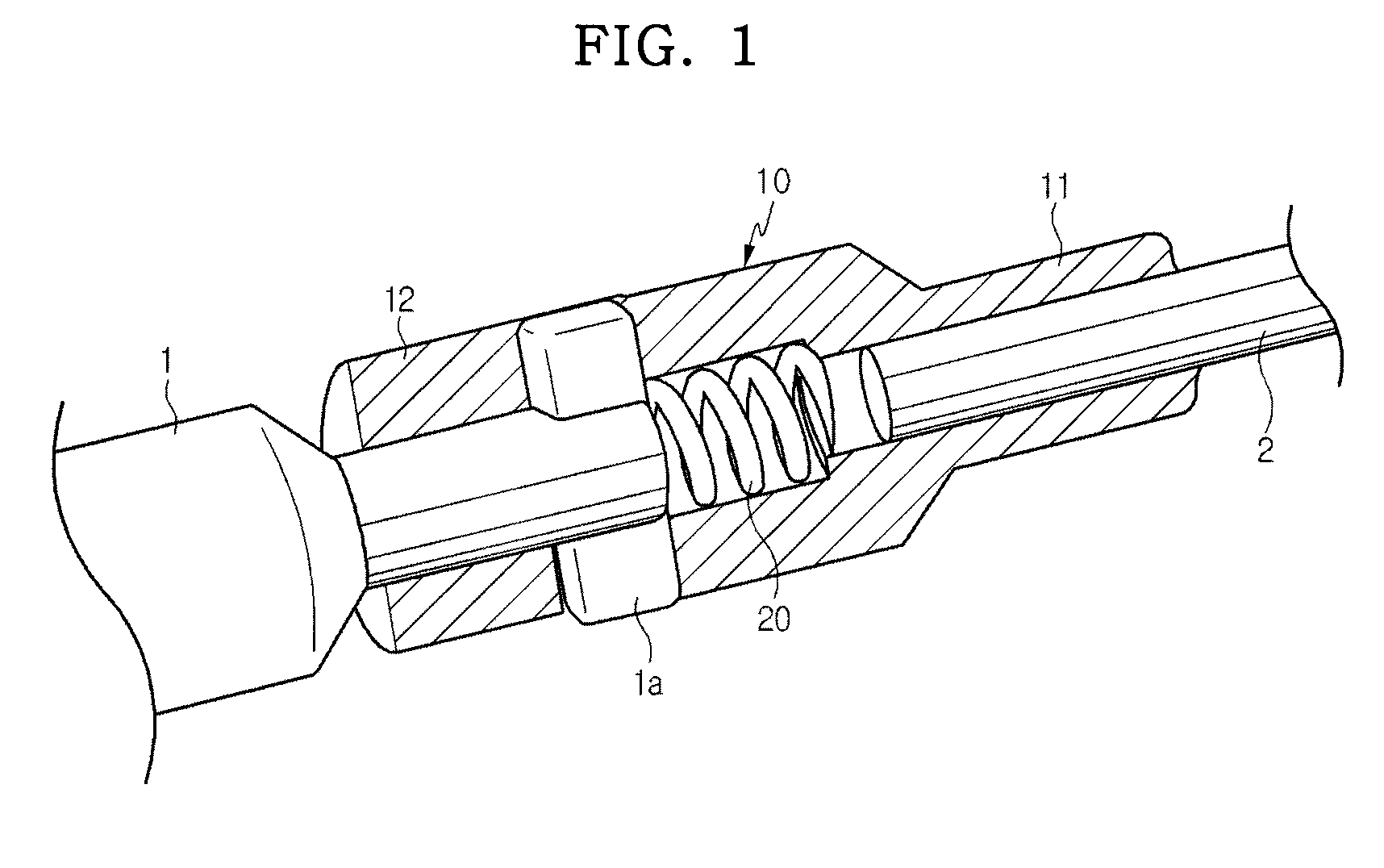
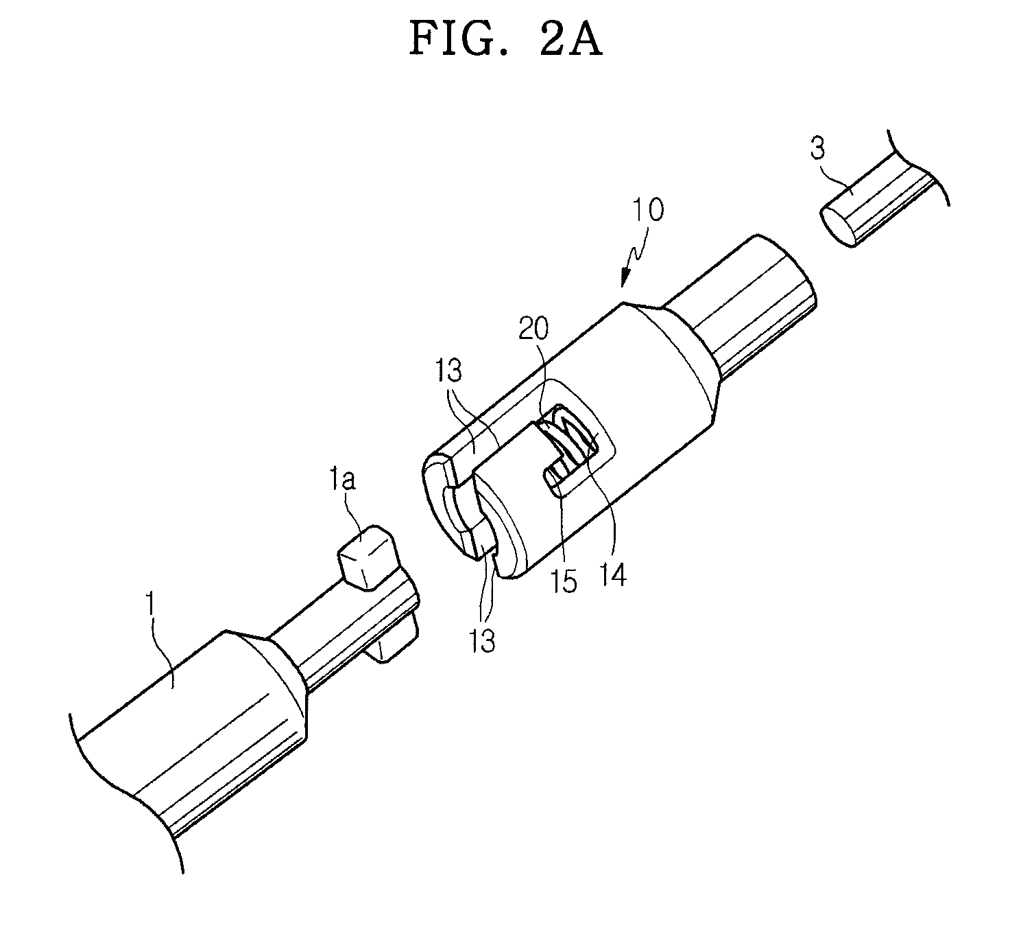
[0018]FIG. 1 is an exploded perspective view illustrating a connecting device of a parking cable for an electric parking brake according to the present invention, and FIGS. 2A to 2C are perspective views illustrating an assembly sequence of the connecting device of the parking cable for the electric parking brake according to the present invention.

[0019]As illustrated in FIGS. 2A to 2C, the connecting device that connects an actuator 1 for the electric parking brake with a parking cable 2 comprises a connector 10 and a reaction force member 20. The connector 10 comprises a small diameter section 11, a large diameter section 12, an axial cutout slit 13, a circumferential cutout slit 14 and a cutout groove 15. The small diameter section 11 has one side into which an outer peripheral surface of the parking cable 2 is inserted. The large diameter section 12 extends from the small...


PUM


Abstract

Disclosed is a connecting device of a parking cable for an electric parking brake, which connects an actuator for the electric parking brake with a parking cable. The connecting device includes a connector and a reaction force member. The connector includes a small diameter section having one side into which an outer peripheral surface of the parking brake is inserted, a large diameter section that extends from the small diameter section to have a diameter larger than that of the small diameter section, an axial cutout slit axially formed through upper and lower surfaces of an outer peripheral portion of the large diameter section such that protrusions circumferentially protruding from the actuator are inserted into the axial cutout slit through the large diameter section, a circumferential cutout slit that extends from an inner end of the axial cutout slit in a circumferential direction, and a cutout groove that axially extends from the circumferential cutout slit. The reaction force member is inserted into the large diameter section to press the protrusions such that the protrusions are seated in the cutout groove through the axial cutout slit and the circumferential cutout slit. According to the connecting device, the assembly work is facilitated, so the assembly efficiency can be improved and connection work using the connector can be easily performed.

Description

CROSS-REFERENCE TO RELATED APPLICATIONS[0001]This application claims the benefit of Korean Patent Application No. 10-2008-0015323, filed on Feb. 20, 2008, in the Korean Intellectual Property Office, the disclosure of which is incorporated herein by reference.BACKGROUND OF THE INVENTION[0002]1. Field of the Invention[0003]The present invention relates to a parking cable for an electric parking brake. More particularly, the present invention relates to a connecting device of a parking cable for an electric parking brake, used for assembling an electric parking brake assembly and a parking cable assembly in a vehicle in a state in which the electric parking brake assembly and the parking cable assembly are separately assembled.[0004]2. Description of the Prior Art[0005]Recently, a parking brake system such as an electronic parking brake (EPB), which automatically operates according to an operation state of a vehicle without manual manipulation of a driver, has been developed.[0006]Acco...

Claims


Application Information

Patent Timeline
IPC IPC(8): F16B7/20
CPCB60T11/046Y10T403/7005Y10T403/32991Y10T403/7007Y10T403/5726Y10T74/20462H01R13/625B60T7/10
Inventor NOH, KANG SUNG
Owner HL MANDO CORP
Learn More