
Anterior lumbar interbody fusion cage device and associated method

a technology of lumbar interbody fusion and cage device, which is applied in the field of anterior lumbar interbody fusion cage device and associated method, can solve the problems of inability to adequately maintain the normal height of the intervertebral space, and achieve the effect of constant cross-sectional shape and constant cross-sectional shap

Active Publication Date: 2009-08-20
CTL MEDICAL CORP
View PDF30 Cites 80 Cited by
  • Summary
  • Abstract
  • Description
  • Claims
  • Application Information

AI Technical Summary

Benefits of technology

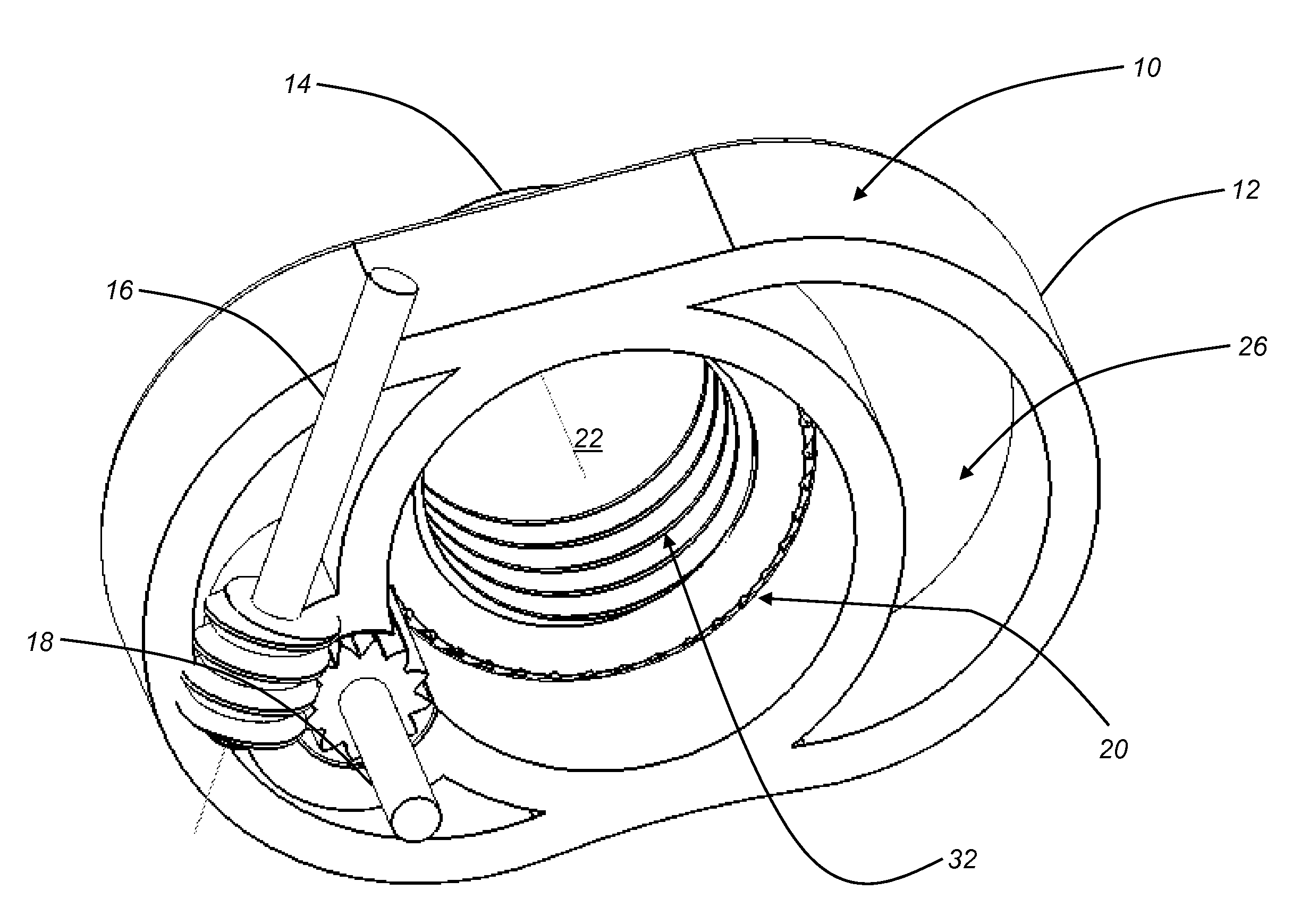
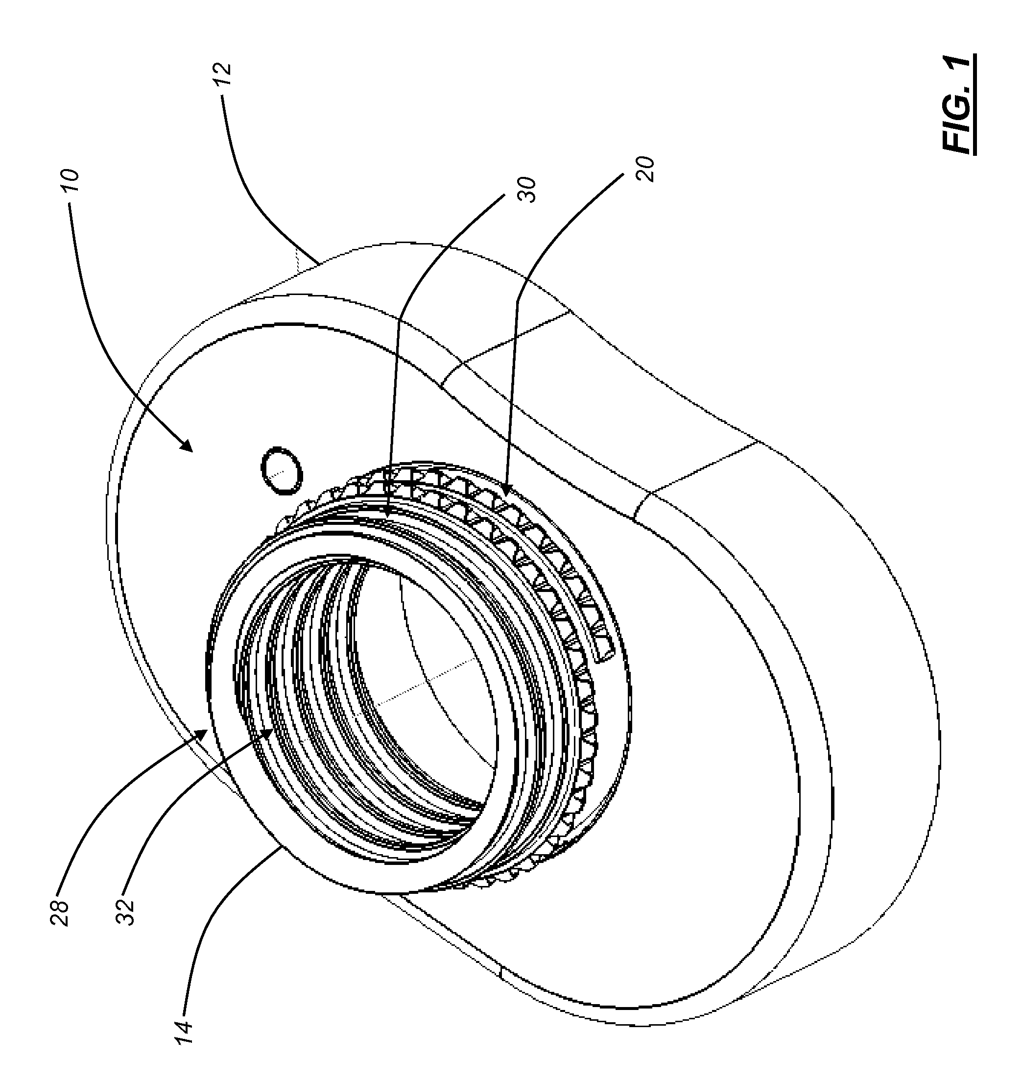
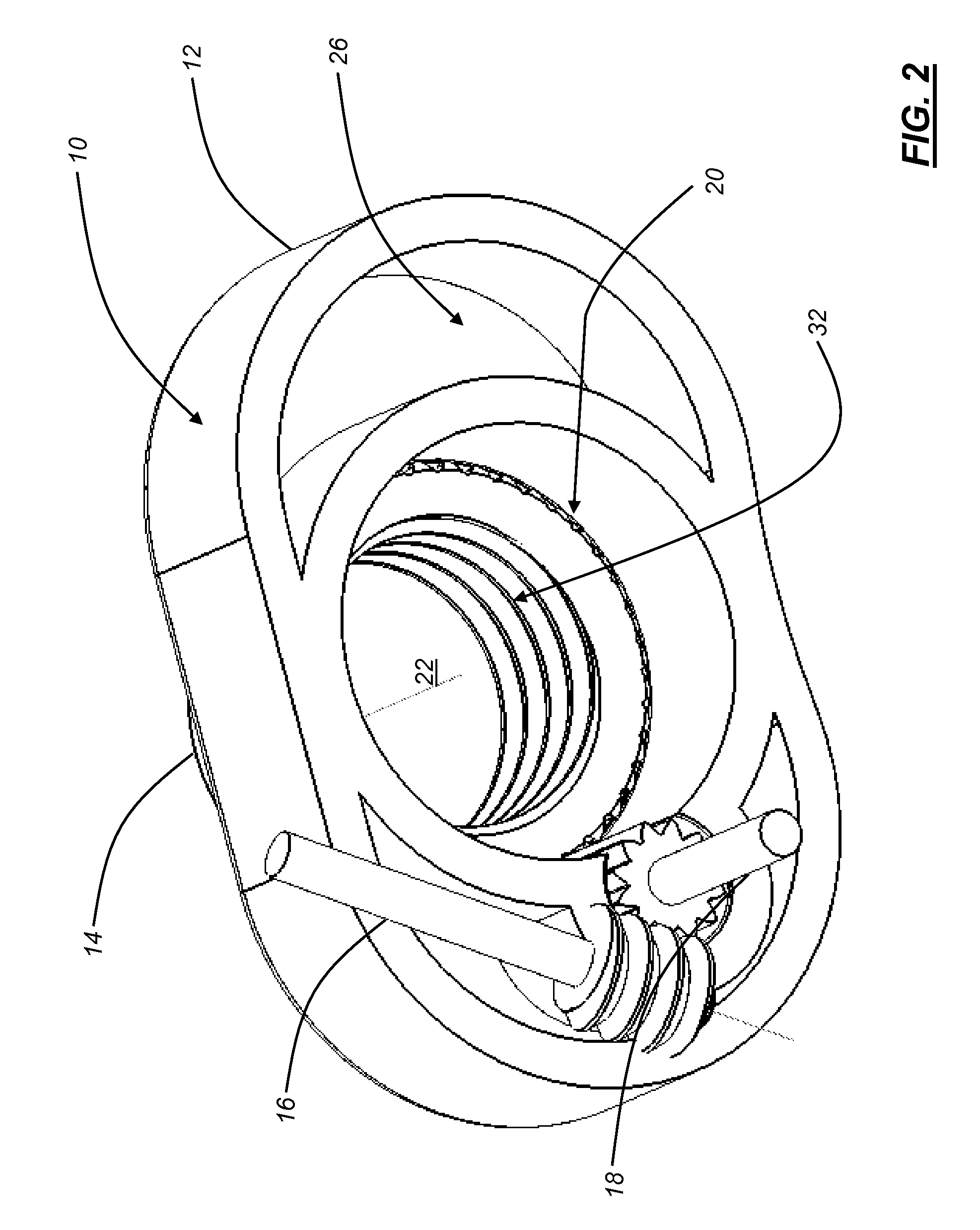
[0005]In various exemplary embodiments, the present invention provides an improved ALIF cage device that has one or more extensible threaded retention pipe structures that are selectively deployed into one or more endplates of adjacent vertebrae once the ALIF cage device is disposed in an intervertebral space of interest. A bone graft is disposed within a housing and the extensible threaded retention pipe structure(s) of the ALIF cage device, as appropriate. Advantageously, the extensible threaded retention pipe structure(s) are selectively deployed into the endplate(s) of the adjacent vertebrae via the actuation of a simple keyed screw and gear mechanism or the like. Again, the fundamental concepts underlying the ALIF cage device of the present invention may be extended to other surgical procedures as well, such as XLIF spinal procedures, cervical spinal procedures, and the like.
[0006]In one exemplary embodiment, the present invention provides a cage device for performing spinal fusion, including: a housing defining one or more ports that is selectively disposed in an intervertebral space between adjacent vertebrae; one or more extensible retention structures that are selectively advanced out of the housing through the one or more ports and into one or more endplates of the adjacent vertebrae; and one or more actuation mechanisms for selectively advancing the one or more extensible retention structures out of the housing through the one or more ports and into the one or more endplates of the adjacent vertebrae. The housing is sized and shaped to cover substantially all of the one or more endplates of the adjacent vertebrae. Optionally, the housing is at least partially manufactured from a radiolucent material. Preferably, the one or more extensible retention structures each consist of an annular structure having a substantially constant cross-sectional shape. The one or more extensible retention structures each include a cutting edge for engaging bony material of an associated endplate of an adjacent vertebrae. The one or more extensible retention structures each also include internal bone threading for engaging bony material of an associated endplate of an adjacent vertebrae. The one or more extensible retention structures each further include external machine threading for engaging corresponding internal machine threading of the housing and selectively advancing the one or more extensible retention structures out of the housing through the one or more ports and into the one or more endplates of the adjacent vertebrae. Preferably, the machine threading is allowed to escape the housing. The machine threading that is allowed to escape the housing serves to compress an associated endplate of an adjacent vertebrae against the housing. In one exemplary embodiment, the one or more actuation mechanisms consist of at least one worm gear/mandrel pair configured to engage the machine threading. Optionally, the one or more actuation mechanisms consist of at least one worm gear/mandrel pair configured to engage longitudinally oriented teeth manufactured into the machine threading. Preferably, the one or more extensible retention structures each include a retention structure configured to prevent that extensible retention structure from escaping the housing. Thus, the one or more extensible retention structures are selectively

Problems solved by technology

All of these retention mechanisms, however, suffer from the shortcomings that they are difficult to place, difficult to deploy, and / or tend to allow the associated cage device and / or bone graft to shift over time and thus fail to adequately maintain the normal height of the intervertebral space, for example.

Method used


Image

  • Anterior lumbar interbody fusion cage device and associated method
  • Anterior lumbar interbody fusion cage device and associated method
  • Anterior lumbar interbody fusion cage device and associated method

Examples


Embodiment Construction

[0016]Referring to FIG. 1, in one exemplary embodiment, the ALIF cage device 10 of the present invention includes a housing 12 and one or more extensible threaded retention pipe structures 14 that are selectively deployed into one or more endplates of adjacent vertebrae once the ALIF cage device 10 is disposed in an intervertebral space of interest. It should be noted that only the top half of the ALIF cage device 10 is illustrated herein (i.e. the top half of the housing 12 and the top extensible threaded retention pipe structure 14). The bottom half of the ALIF cage device 10 is substantially identical, including the bottom half of the housing 12 and the bottom extensible threaded retention pipe structure 14, when used. The top and bottom halves of the ALIF cage device 10 (i.e. the top and bottom halves of the housing 12) are joined during the manufacturing process or prior to implantation to form an integrated whole. A bone graft is disposed within the housing 12 and the extensib...


PUM


Abstract

The present invention provides a cage device for performing spinal fusion, including: a housing defining one or more ports that is selectively disposed in an intervertebral space between adjacent vertebrae; one or more extensible retention structures that are selectively advanced out of the housing through the one or more ports and into one or more endplates of the adjacent vertebrae; and one or more actuation mechanisms for selectively advancing the one or more extensible retention structures out of the housing through the one or more ports and into the one or more endplates of the adjacent vertebrae. In one exemplary embodiment, the one or more actuation mechanisms consist of at least one worm gear / mandrel pair. The one or more extensible retention structures are selectively advanced out of the housing through the one or more ports and into the one or more endplates of the adjacent vertebrae with a rotational motion. Preferably, the one or more extensible retention structures are configured such that they may contain a bone graft. In one exemplary embodiment, the housing is selectively disposed in the intervertebral space between the adjacent vertebrae using an anterior approach.

Description

CROSS-REFERENCE TO RELATED APPLICATION(S)[0001]The present non-provisional patent application claims the benefit of priority of U.S. Provisional Patent Application No. 61 / 028,624, filed on Feb. 14, 2008, and entitled “ANTERIOR LUMBAR INTERBODY FUSION CAGE DEVICE,” the contents of which are incorporated in full by reference herein.FIELD OF THE INVENTION[0002]The present invention relates generally to devices and methods for performing spinal surgery. More specifically, the present invention relates to an anterior lumbar interbody fusion (ALIF) cage device and an associated method for performing fusion procedures of the lumbar spine. The fundamental concepts underlying this device and method may be extended to other surgical procedures as well, such as extreme lateral interbody fusion (XLIF) spinal procedures, cervical spinal procedures, and the like.BACKGROUND OF THE INVENTION[0003]ALIF is a spinal fusion procedure that utilizes an anterior (i.e. frontal) approach through the abdomin...

Claims


Application Information

Patent Timeline
IPC IPC(8): A61F2/44
CPCA61F2/4465A61F2002/2835A61F2002/3008A61F2002/30525A61F2250/0098A61F2002/30841A61F2002/3085A61F2002/4475A61F2220/0025A61F2002/30579A61F2002/30593
Inventor SLEDGE, JOHN B.
Owner CTL MEDICAL CORP
Learn More