Joint For Industrial Robots

a robot and joint technology, applied in the field of joints, can solve the problems of high weight relative stiffness and high need for joints with higher stiffness pro kg, and achieve the effects of large angular working range, high stiffness, and large interface surfaces

Inactive Publication Date: 2009-08-27
ABB (SCHWEIZ) AG
View PDF2 Cites 38 Cited by
  • Summary
  • Abstract
  • Description
  • Claims
  • Application Information

AI Technical Summary

Benefits of technology

[0008]Since the socket parts through the biasing means are clamped towards the male unit it is attained that the contact force between the male and the female units will be distributed on the complete contact surface. Thereby the surface pressure conditions become more favourable in comparison with a ball- or cylinder bearing. The result is that the joint becomes much more stiff for a given dimension. By the arrangement of clamping the socket parts the joint will have a high stiffness in relation to its weight.
[0045]Using aluminium as material for the joint unit contributes to achieve a high stiffness to weight ratio for the joint.

Problems solved by technology

However, using joints built up from ball- or roller bearings gives high weight relative stiffness.
Thus, joints with higher stiffness pro kg is very much needed since high weight of the moving parts of the robot means low natural frequencies and constraints in robot performance.

Method used


Image

  • Joint For Industrial Robots
  • Joint For Industrial Robots
  • Joint For Industrial Robots

Examples


Embodiment Construction

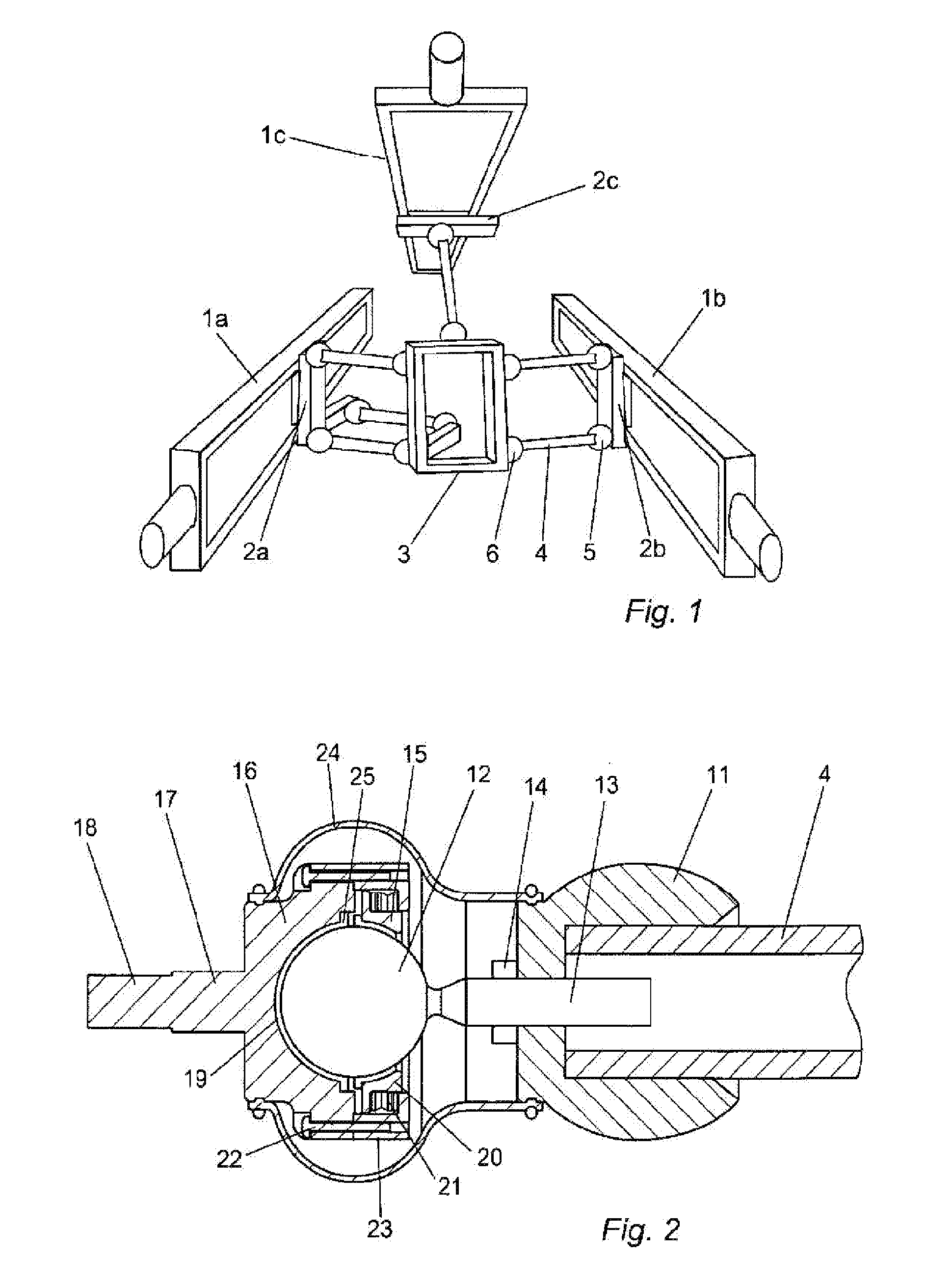
[0071]FIG. 1 schematically illustrates a parallel kinematic robot with six links, where the links transmit forces between actuators and a platform. Three linear actuators 1a, b and c move three carts 2a, b and c along three linear guide ways. The carts are connected to a platform 3 via links with joints in each end. Each link consists of a rod 4, of which one joint 5 connects it to the cart 2b and another joint 6 connects it to the platform 3. Both joints can have three degrees of freedom in this link configuration of the parallel kinematics robot. However it will work also with two degrees of freedom for each joint even if the link assembly then will be over constrained, which can lead to the introduction of residual torques in the links. Often a design with three degrees of freedom joints at the cart side is used and with two degrees of freedom joints at the platform side.

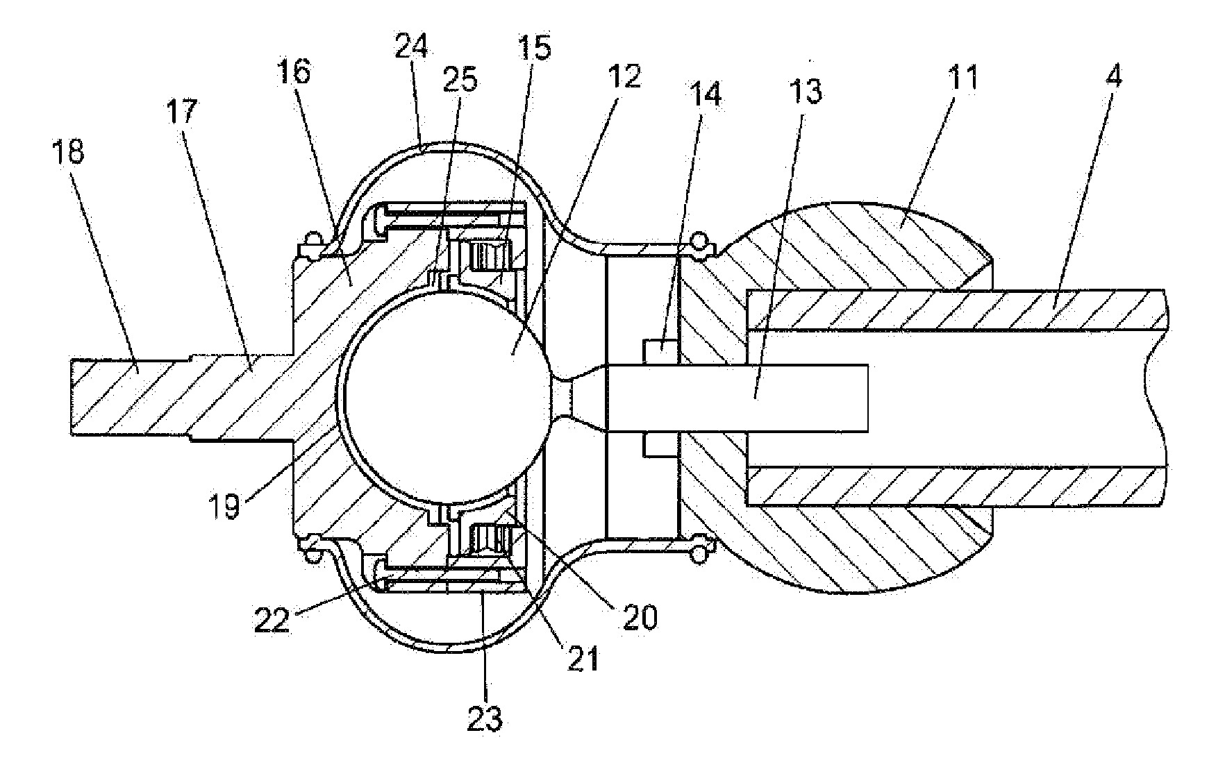
[0072]FIG. 2 shows a new link design with joints according to the invention. The link consists of a carbon tub...


PUM


Abstract

The invention relates to a joint having a male unit and a female unit. The external surface of the male unit is of complementary shape to the internal surface of the female unit. The units cooperate and have shapes allowing rotational movement in at least one degree of freedom of the male unit within the female unit. The female unit has two socket parts. According to the invention biasing means is provided for biasing each of the socket parts towards the male unit.

Description

CROSS-REFERENCE TO RELATED APPLICATIONS[0001]The present application is a continuation of pending International patent application PCT / EP2007 / 061962 filed on Nov. 7, 2007 which designates the United States and claims priority from U.S. provisional patent application 60 / 857,482 filed on Nov. 8, 2006, the content of which is incorporated herein by reference.FIELD OF THE INVENTION[0002]The present invention relates to a joint comprising a male unit and a female unit, the external surface of the male unit being of complementary shape to the internal surface of the female unit for cooperation therewith and having a shape allowing rotational movement in at least one degree of freedom of the male unit within the female unit, the female unit comprising at least two socket parts.BACKGROUND OF THE INVENTION[0003]In order to transmit forces between two relative each other movable objects a link with a joint in each end is needed. One important application for this kind of transmission is paral...

Claims


Application Information

Patent Timeline
Patent Type & Authority Applications(United States)
IPC IPC(8): B25J17/00F16C11/06
CPCB25J17/0266F16C11/0647F16C11/086Y10T74/20317Y10T74/20329Y10T403/32762B25J9/0072
Inventor BROGARDH, TORGNYKULLBORG, OVEODE, OVE
Owner ABB (SCHWEIZ) AG
Why Eureka
Try Eureka