Method and Apparatus for Repositioning Flow Elements In a Tapered Flow Structure

a flow element and tapered flow technology, applied in the direction of filtration separation, multi-stage water/sewage treatment, separation processes, etc., can solve the problems of membrane fouling, the buildup of rejected solutes and particulates cannot be effectively removed,

Active Publication Date: 2009-08-27
BEN GURION UNIVERSITY OF THE NEGEV
View PDF10 Cites 22 Cited by
  • Summary
  • Abstract
  • Description
  • Claims
  • Application Information

AI Technical Summary

Benefits of technology

[0011]In a first aspect, the present invention provides a method for operating a tapered flow pressure driven arrangement containing a plurality of membrane modules, which comprises positioning said membrane modules in at least two successively arranged flow stages (which sequence of flow stages is conveniently designated {Si}), such that the number of membrane modules operating in parallel in a given flow stage is greater than their number in the consecutive flow stage (the number of membrane modules operating in parallel within a particular stage Si is conveniently designated Ni), passing a feed stream through a flow stage to generate a permeate and a concentrate, directing said concentrate to the consecutive flow stage and passing said concentrate therethrough, while periodically replacing one or more of the membrane modules belonging to said consecutive flow stage with one or more membrane modules belonging to the previous flow stage, wherein the periodicity of said replacement is such that the surface of membranes disposed in said membrane modules is exposed to super-saturation conditions associated with the passage of said concentrate for a period of time that is shorter than the time required for said concentrate to precipitate therefrom one or more sparingly soluble salts and / or minerals onto the surface of the membranes in said consecutive flow stage under said super-saturation conditions, or before deposit of organic substances can occur in the first of said two or more successively arranged flow stages.

Problems solved by technology

If the flow rate is reduced below a certain level, then the buildup of rejected solutes and particulate matter on the membrane surface cannot be effectively removed by the tangential flow and shear forces of the fluid flowing largely parallel to the membrane surface.
This buildup can lead to fouling of the membrane.

Method used


Image

  • Method and Apparatus for Repositioning Flow Elements In a Tapered Flow Structure
  • Method and Apparatus for Repositioning Flow Elements In a Tapered Flow Structure
  • Method and Apparatus for Repositioning Flow Elements In a Tapered Flow Structure

Examples


Embodiment Construction

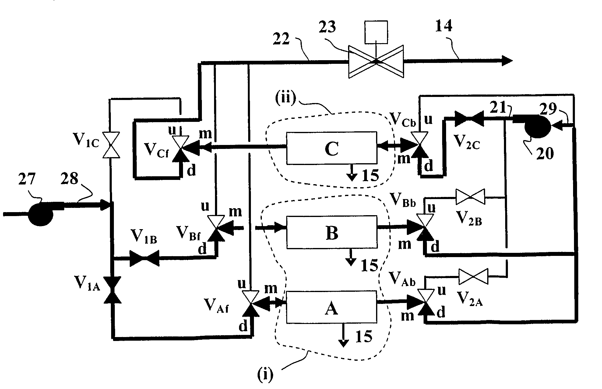
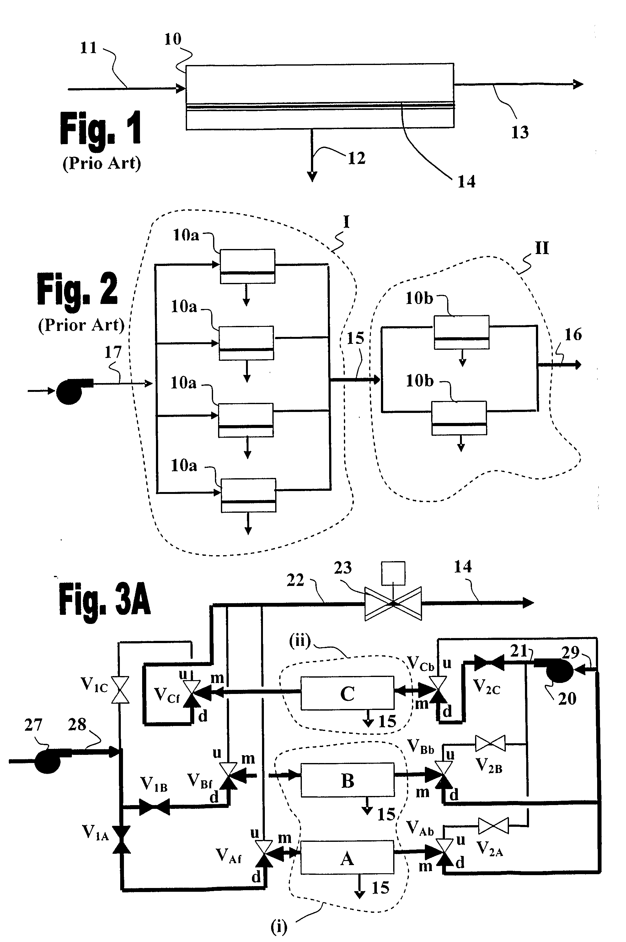
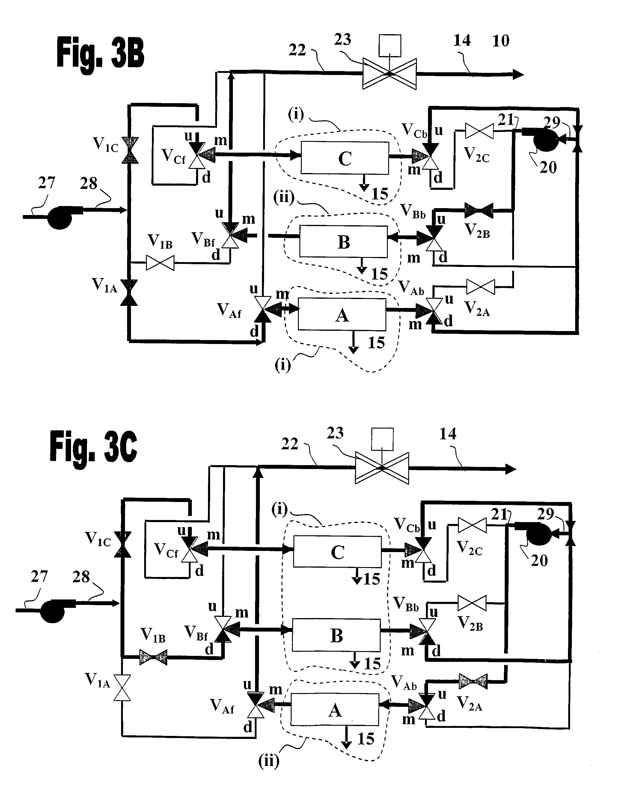
[0037]In general, the present invention provides a system and method for repositioning sets of flow modules (e.g., membrane modules) in a tapered flow structure. More particularly, the present invention provides means and methods for repositioning blocks of membrane modules in a tapered-flow pressure driven membrane process, such that blocks of membrane modules receiving the most concentrated process fluid can be periodically repositioned to the position of the least concentrated process fluid. Advantageously, the repositioning of membrane modules blocks is performed within time intervals smaller than the time required for the start of precipitation fouling (i.e., less than the induction time τ), and / or within time intervals smaller than the time required for serious biofouling or organic fouling caused due to deposition of organic substances. A detailed definition of the induction time and methods for estimating the same are given hereinbelow, after the description of the drawings....


PUM

PropertyMeasurementUnit
diameteraaaaaaaaaa
flow rateaaaaaaaaaa
solubilityaaaaaaaaaa

Abstract

A method for operating a tapered flow pressure driven arrangement containing a plurality of membrane modules, which comprises positioning said membrane modules in at least two successively arranged flow stages, such that the number of membrane modules operating in parallel in a given flow stage is greater than their number in the consecutive flow stage, passing a feed stream through a flow stage to generate a permeate and a concentrate, directing said concentrate to the consecutive flow stage and passing said concentrate therethrough, while periodically replacing one or more of the membrane modules belonging to said consecutive flow stage with one or more membrane modules belonging to the previous flow stage, wherein the periodicity of said replacement is such that the surface of membranes disposed in said consecutive flow stage is exposed to super-saturation conditions associated with the passage of said concentrate for a period of time that is shorter than the time required for said concentrate to precipitate therefrom one or more sparingly soluble salts and/or minerals, onto the surface of the membranes in said consecutive flow stage under said super-saturation conditions, or before deposit of organic substances can occur in the first of said two or more successively arranged flow stages. An apparatus for carrying out the aforementioned method is also provided.

Description

[0001]Many pressure driven operations, such as shown in FIG. 1A, are described by a process as cross-flow or tangential flow filtration in which a feed 11 directed into a membrane module 10 is passed in parallel to the surface of membrane 14 wherein it is split into two streams. The first stream 12 is the permeate which passes across a selective membrane barrier 14, and the remaining high pressure stream 13 which exits module 10 at the other end is the concentrate. A serial membrane module structure may contain two or more membrane modules connected in series wherein the concentrate of one module forms the feed flow of the next module downstream. As more and more of the fluid is passed through the membrane modules the flow rate of the concentrate 13 is gradually reduced.[0002]If the flow rate is reduced below a certain level, then the buildup of rejected solutes and particulate matter on the membrane surface cannot be effectively removed by the tangential flow and shear forces of th...

Claims


Application Information

Patent Timeline
Patent Type & Authority Applications(United States)
IPC IPC(8): B01D63/00B01D61/00
CPCB01D61/022B01D61/025B01D61/027B01D61/14B01D2321/2083B01D61/145B01D61/147B01D65/08B01D2321/04B01D61/142B01D61/146B01D61/026
Inventor GILRON, JACK L.
Owner BEN GURION UNIVERSITY OF THE NEGEV
Why Eureka
Try Eureka