Method for three-dimensional presentation of a moved structure using a tomographic method

Active Publication Date: 2009-08-27
SIEMENS HEALTHCARE GMBH
View PDF8 Cites 15 Cited by
  • Summary
  • Abstract
  • Description
  • Claims
  • Application Information

AI Technical Summary

Benefits of technology

[0010]It has proved advantageous if, for three-dimensional presentation of each projection angle with node point, only that projection image is selected in wh

Problems solved by technology

This however is not the case with C-arm computer tomography.

Method used


Image

  • Method for three-dimensional presentation of a moved structure using a tomographic method
  • Method for three-dimensional presentation of a moved structure using a tomographic method
  • Method for three-dimensional presentation of a moved structure using a tomographic method

Examples


Embodiment Construction

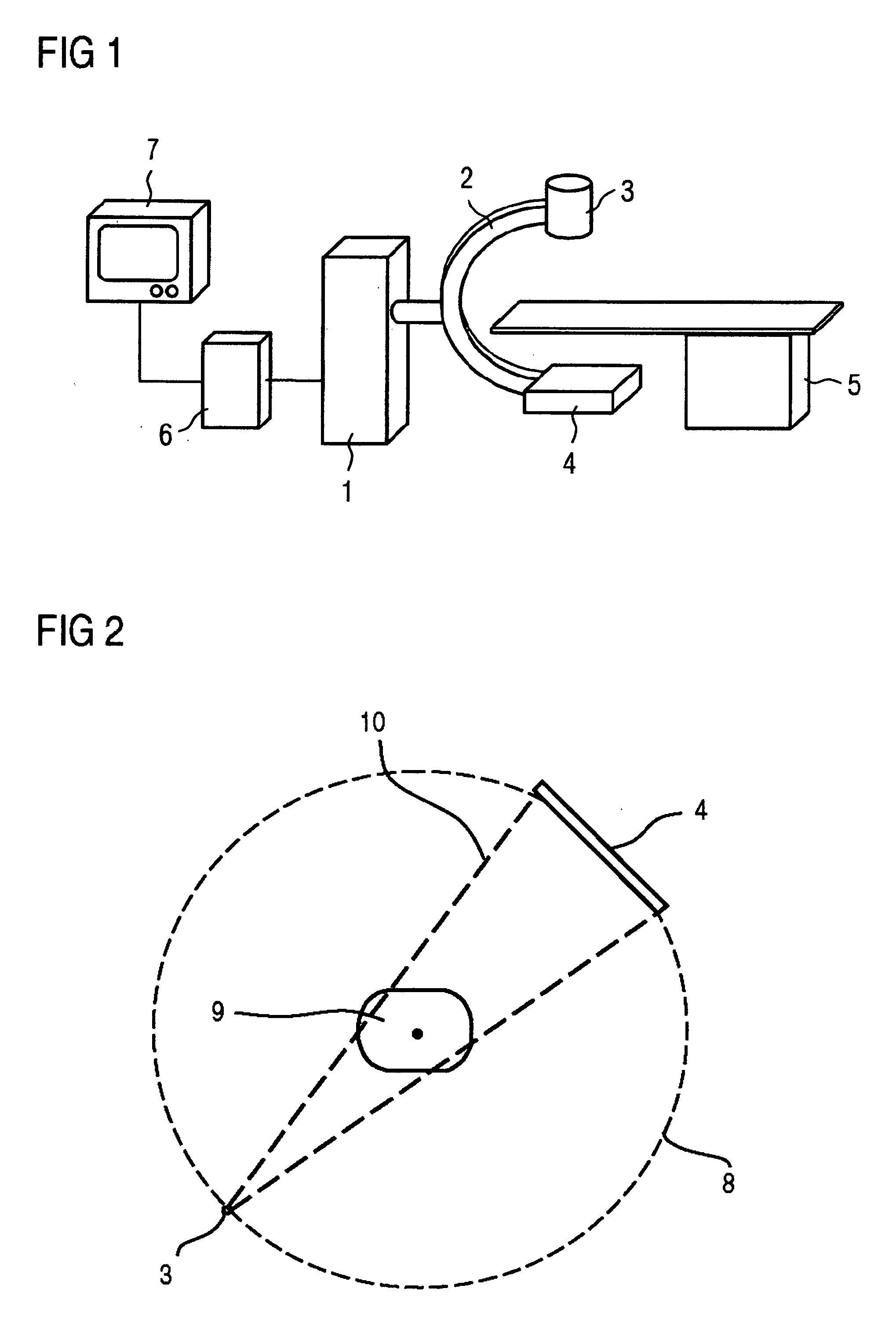
[0033]US 2006 / 0120507 A1 discloses this type of x-ray diagnostic device for executing the method for angiography which is shown for example in FIG. 1, which features a C-arm 2 supported to allow it to rotate on a stand 1, at the ends of which an x-ray radiation source, for example an x-ray emitter 3, and an x-ray image detector 4 are arranged.

[0034]The x-ray image detector 4 can be a rectangular or square flat semiconductor detector, which is preferably made of amorphous silicon (a-Si).

[0035]In the optical path of the x-ray tube assembly 3 is a patient support table 5 for recording images, of a heart of a patient to be examined for example. Connected to the x-ray diagnostic device is an imaging system 6 which receives and processes the image signals of the x-ray image detector 4. The x-ray images can then be viewed on a monitor 7.

[0036]If 3D data sets are to be created, the rotatably-supported C-arm 2 with x-ray source 3 and x-ray detector 4 is turned so that, as shown schematically...


PUM


Abstract

The invention relates to a method for three-dimensional presentation of a moved structure using a tomographic method, in which a plurality of projection images are recorded from different imaging angles between a start angle with a start node point and an end angle with an end node point by an imaging unit during a number of rotation passes, with three-dimensional image data being able to be reconstructed from the projection images, with the projection images being spaced by a path or an edge. For determining the three-dimensional presentation for each angle of projection only those projection images are selected which minimize the sum of the paths or weighted edges between adjacent projection angles for a gating.

Description

CROSS REFERENCE TO RELATED APPLICATIONS[0001]The present application claims the benefit of a provisional patent application filed on Feb. 19, 2008, and assigned application No. 61 / 029,603. The present application also claims the benefit of a German application No. 10 2008 010 006.4 filed Feb. 19, 2008. Both of the applications are incorporated by reference herein in their entirety.FIELD OF THE INVENTION[0002]The invention relates to a method for three-dimensional presentation of a moved structure using a tomographic method.BACKGROUND OF THE INVENTION[0003]The invention relates to the 3D image reconstruction of dynamic objects from 2D projection images. The theory of image reconstruction demands a set of projection images of a stationary object over projection angles in the range of 200° (180°+cone angle). With a dynamic object an attempt is made to emulate a stationary object from said object. The imaging of the heart uses only the projection data that belongs to the heart phase dur...

Claims


Application Information

Patent Timeline
IPC IPC(8): G06K9/00
CPCA61B6/032A61B6/4441G06T2211/412G06T11/005A61B6/466
Inventor HORNEGGER, JOACHIMLAURITSCH, GUNTERPRUMMER, MARCUSROHKOHL, CHRISTOPHER
Owner SIEMENS HEALTHCARE GMBH
Why Eureka
Try Eureka