Assembly of a microfluidic device for analysis of biological material
Active Publication Date: 2009-08-27
STMICROELECTRONICS SRL
13 Cites 37 Cited by
AI-Extracted Technical Summary
Problems solved by technology
As an example, in DNA-based blood analyses, samples are often purified by filtration, centrifugation or by el...
Abstract
In a microfluidic assembly, a microfluidic device is provided with a body in which at least a first inlet for loading a fluid for analysis, and a buried area in fluid communication with the first inlet are defined. An analysis chamber is in fluid communication with the buried area and an interface cover is coupled in a fluid-tight manner above the microfluidic device. The interface cover is provided with a sealing portion in correspondence to the analysis chamber, operable to assume a first configuration, in which it leaves the analysis chamber open, and a second configuration, in which it closes the analysis chamber in a fluid-tight manner.
Application Domain
SamplingLaboratory glasswares +4
Technology Topic
EngineeringBiological materials
Image
Examples
- Experimental program(1)
Example
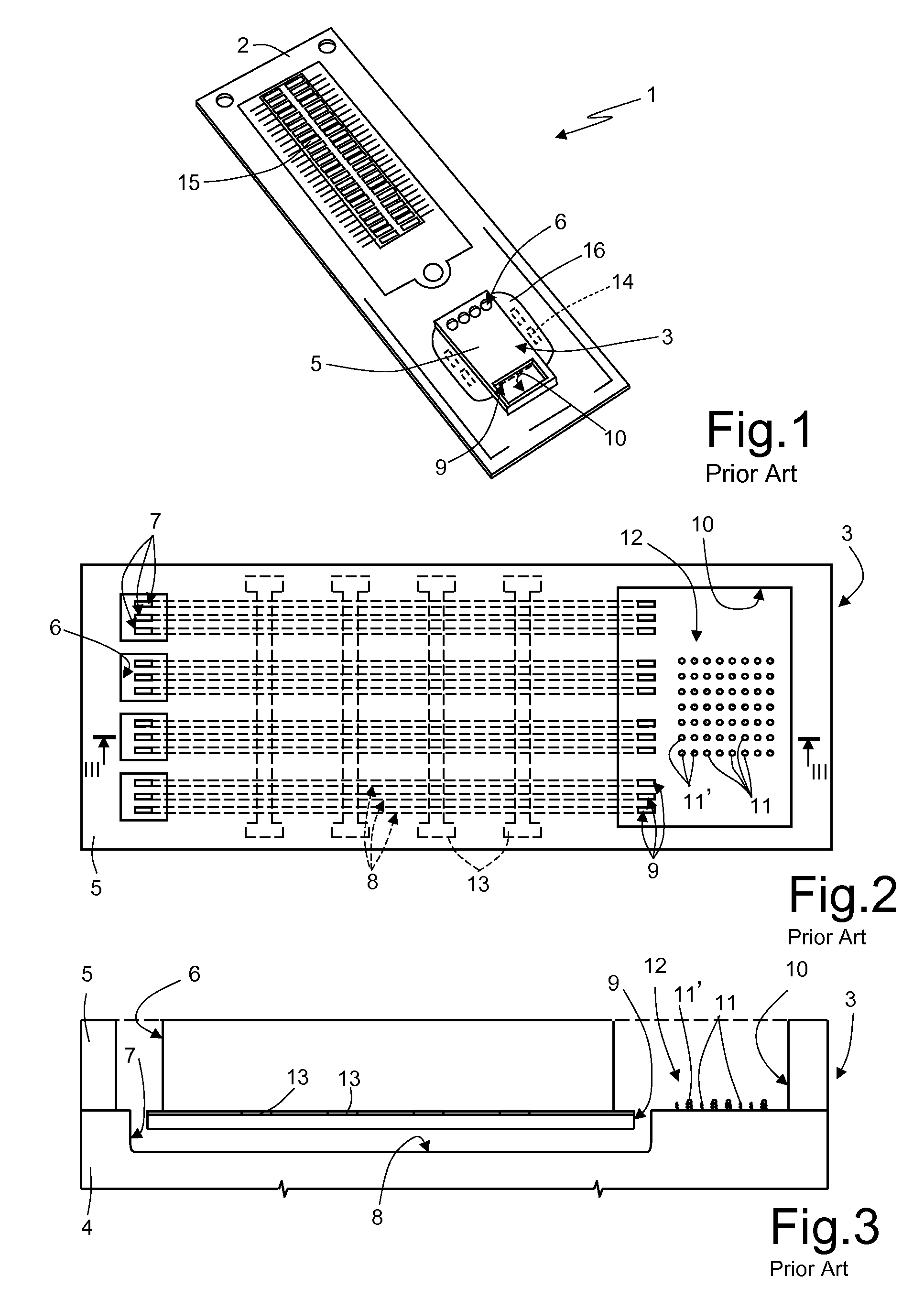
[0037]The previously described integrated microfluidic devices, although allowing rapid and economic analysis of biological material samples, are not completely optimized, exhibiting certain problems in the structure and in the manufacturing process.
[0038]First of all, the use of the structural layer 5 made of glass is particularly expensive and also requires additional process steps for its coupling (for example, via bonding techniques) to the substrate 4.
[0039]The structural layer 5 is usually open to the outside at the substrate inlets and outlets and the detection chamber (except where the above-mentioned clips are used). Accordingly, the risk of contamination exists for the biological material contained inside the microfluidic device. The elastic clips must be applied manually by the user during predefined steps of the biological material analysis cycle; any positioning error can therefore cause contamination and compromise the results of the analysis. Due to the high temperatures developing during the heating cycles, the clips and the associated gaskets may not guarantee perfect sealing and, in the worst case, could cause the material to leak out.
[0040]In addition, the loading of biological material must be carried out manually by an operator, using a standard type of pipette, directly onto the microfluidic die 3 at the inlet reservoirs 6 and the associated substrate inlets 7. This operation is difficult due to the small dimensions and, in particular, the small distance separating the inlets.
[0041]As shown in FIGS. 4 and 5, a microfluidic assembly 20 according to a first embodiment of the present invention comprises a microfluidic device 1′, a structural cover 22 on the microfluidic device 1′, an interface cover 23 on the structural cover, and a first and second cap 24 and 25 coupled to, and arranged on, the interface cover. Connection elements 26, screws or rivets for example, inserted in purposely provided coupling holes 27 formed at corresponding points in the various layers, connect and couple the microfluidic device 1′, structural cover 22 and interface cover 23 together. The microfluidic device 1′, structural cover 22 and interface cover 23 have a generally parallelepipedal shape with a main extension direction and have a middle axis A.
[0042]In detail, in a manner substantially similar to the device described with reference to FIGS. 1-3, so that parts similar to others already described are denoted with the same reference numbers, the microfluidic device 1′ comprises a base support 2 (in particular, a PCB—Printed Circuit Board, or a glass, ceramic or metal sheet or a flexible tape) and a microfluidic die 3′. The microfluidic die 3′ is carried on the base support 2 at one of its ends, and the base support 2 carries the necessary input/output electrical connections. In particular, the microfluidic die 3′ differs from that illustrated in FIGS. 1-3 due to the fact that it does not include a structural layer, of glass in particular, positioned above the substrate 4 and in which the microfluidic channels 8 are buried. The microfluidic die 3′ still comprises the substrates inlets and outlets 7 and 9 coupled to the microfluidic channels 8.
[0043]According to an embodiment of the present invention, the structural cover 22 is substantially symmetrical with respect to the middle axis A (see also FIG. 6) and defines on the microfluidic die 3′ all the openings/chambers traditionally defined by the structural glass layer and, in particular: inlet reservoirs 6′ (substantially equivalent to the inlet reservoirs 6 in FIG. 3) in fluid communication with the substrate inlets 7, and a detection chamber 10′ (substantially equivalent to the detection chamber 10 in FIG. 3), in fluid communication with the substrate outlets 9. The structural cover 22 is made of an elastomeric material (for example, a silicone gel, such as Sylgard®) and has a thickness, for instance, of 500 μm. Housing openings 29 are also made in the structural cover 22, lateral to the microfluidic die 3′, for receiving the side covers 16 of the electrodes of the heating elements associated with the microfluidic channels 8 (refer to FIGS. 1-2, as well).
[0044]The interface cover 23 is made of glass, ceramic, metal or preferable transparent plastic (Lexan® for example) and has a series of features that facilitate external interfacing with the microfluidic device 1′ and also, in certain operating conditions, allow sealing to be achieved on certain areas of the device.
[0045]In detail, as can also be seen in FIG. 7, which shows its lower surface 23a that contacts the underlying structural cover 22, the interface cover 23, also substantially symmetrical with respect to the middle axis A, includes a channel arrangement 30, above and in fluid communication with the inlet reservoirs 6′; the channel arrangement 30 connects the inlet reservoirs 6′ with inlet holes 32 formed through the interface cover 23. As will be described further on, access from the outside to the microfluidic device 1′ is achieved through the inlet holes 32. In particular, the channel arrangement 30 is configured to redistribute the inlets to the microfluidic device 1′, to obtain a desired arrangement of the inlet holes 32, different from the original layout of the substrate inlets 7.
[0046]In greater detail, the channel arrangement 30 comprises a plurality of inlet channels 33, for example in numbers matching the number of the inlet reservoirs 6′, formed as recesses into the inside of the interface cover 23, in such a manner that they are defined by the same interface cover 23 with regards to respective upper and side walls, and by the underlying structural cover 22 with regards to a respective lower wall. The inlet channels 33 start at the inlet reservoirs 6′ and terminate at the inlet holes 32, and are configured so that the inlet holes 32 are spaced a greater distance apart (for example, even an order of magnitude greater) than a corresponding distance of separation between the inlet reservoirs 6′. In addition, the inlet channels 33 all usefully have the same length (between a respective inlet hole 32 and a corresponding inlet reservoir 6′), so as to guarantee filling the channels with an identical amount of fluid (as described further on).
[0047]The interface cover 23 also includes, in correspondence to the detection chamber 10′, a mobile structure 35 provided with freedom of movement in a vertical direction, orthogonal to the lower surface 23a of the interface cover.
[0048]In detail, also with reference to FIGS. 8A-8C, the mobile structure 35 is housed in a cavity 36 that traverses the interface cover 23 for its entire thickness, and includes a connection element 35a connected to the interface cover 23 and a body element 35b integral with the connection element 35a; the mobile structure 35 is thus surrounded on three sides by the cavity 36. In particular, the thickness of the connection element 35a is less than that of the body element 35b, which is in turn, less than that of the interface cover 23. The body element 35b also has a central sealing element 37, made of an elastomeric material, silicone for instance, embedded into the body element and slightly protruding from it at the lower surface 23a. In particular, the sealing element 37 is made by hardening of silicone material (starting from a liquid gel for example), using the body element 35b as a mould. In fact, as shown in the exploded diagram in FIG. 4, when uncoupled from the sealing element 37, the body element 35b has upper and lower recesses 38a communicating via a through hole 38b; the sealing element 37 is formed by filling the recesses 38a and the through hole 38b with the silicone material.
[0049]The mobile structure 35 also has a tongue 39 integral with, and extending to form a projecting part from, an end surface of the body element 35b, opposite to the connection element 35a. The tongue 39 has an inclined surface 39a connecting with the body element 35b, and forming an acute angle with the lower surface 23a of the interface cover.
[0050]In use, the body element 35b of the mobile structure 35 is arranged at rest above the detection chamber 10′ without touching the structural cover 22; furthermore, the sealing element 37 is positioned partially inside the detection chamber 10′ above the substrate outlets 9, without however touching the substrate 4 of the microfluidic die 3′. In this operating condition, a gap 40 is thus present between the body element 35b and the sealing element 37, and the detection chamber 10′ and the substrate outlets 9, which are therefore open at the top. As described in detail further on, the application of a force/pressure on the mobile structure 35 makes the body element 35b and the associated sealing element 37 move towards the structural cover 22, sealing the detection chamber 10′, with the body element 35b abutting against the structural cover 22, and the sealing element 37 abutting directly against the substrate outlets 9 of the substrate 4.
[0051]The interface cover 23 also includes a plurality of washing openings—made of respective through holes that traverse the interface cover, and of respective channel portions formed in the lower surface 23a of the interface cover—for loading/extracting a washing fluid into/from the detection chamber 10′. In detail, there is a washing inlet 41a, arranged along the middle axis A in a position facing the tongue 39, and two washing outlets 41b arranged lateral to the body element 35b, on opposite sides with respect to the middle axis A. In particular, the washing inlet 41a and the washing outlets 41b are connected to the cavity 36 through respective washing channels 42 formed in the interface cover 23.
[0052]Moreover, the interface cover has a substantially flat upper surface 23b.
[0053]The first cap 24 is arranged above the interface cover 23 in correspondence to the inlet holes 32, and is made, for example, of a plastic material. In detail, two series of filling holes 43a and 43b, located on opposite sides of the cap 24, are formed through the first cap 24; the layout of the filling holes of each series reproduces the layout of the inlet holes 32. Furthermore, the filling holes 43a and 43b, like the inlet holes 32, are shaped so as to facilitate the insertion of a suitable fluid-loading element, for example, a pipette or syringe. As will be clarified further on, a first series of filling holes 43a is to be used for loading biological material inside the microfluidic device 1′, while the second series of filling holes 43b is to be used for loading a buffer solution (water and salt for example); the two series of filling holes 43a and 43b are separate and distinct in order to avoid contamination due to fluid residues.
[0054]The first cap 24 is coupled to the interface cover 23 so that it is free to rotate around an axis orthogonal to the upper surface 23b of the interface cover. In detail, the first cap 24 is coupled via a bushing 44a and a pivot pin 44b that rests on the structural cover 22, traverses the interface cover 23, and engages in a coupling hole 45 formed at the center of the first cap 24. In addition, a protuberance 46 of the first cap 24 cooperates with a locking pin 47 that protrudes from the interface cover 23 to stop rotary movement of the first cap 24. In use, as will be described in detail further on, the first cap 24 is turned with rotary movements of given angular excursion (equal to 90° for example) to align the filling holes 43a and 43b of the first and the second series with the inlet holes 32 and thus allow fluids (e.g., biological material and buffer solution) to be loaded inside the microfluidic device 1′.
[0055]The second cap 25 is arranged above the interface cover 23 in correspondence to the washing openings and has a plurality of washing holes, the layout of which reproduces that of the washing inlets and outlets 41a and 41b. Thus, there is a inlet washing hole 49a on the middle axis A in correspondence to one end of the second cap 25, and two outlet washing holes 49b arranged laterally and on opposite sides with respect to the middle axis A. In a central position, between the outlet washing holes 49b, there is an actuation hole 50, the function of which will be clarified further on.
[0056]The second cap 25 is slidingly movable, within purposely provided guides 51 carried on the upper surface 23b of the interface cover 23, due to the action of an actuator (not shown); in particular, the second cap 25 is movable between at least a closed position in which the washing holes are not aligned with the washing openings and an open position in which the washing holes are aligned with the same washing openings.
[0057]In use, the connection elements 26 exert light compression on the structural cover 22, in order to achieve the required sealing between the microfluidic device 1′ and the interface cover 23, both of which are rigid elements. To this end, the connection elements 26 can include spacer elements that, through their height, control the level of compression on the structural cover 22, which acts as a sealing gasket. The ends of the connection elements 26 can be welded, glued or riveted to the base support 2.
[0058]As schematically shown in FIG. 9, an analysis system 52 cooperating with the microfluidic assembly 20 is implemented through a computer system and comprises: a loading device 53, configured to control loading of fluids inside the microfluidic device 1′; a temperature control device 54, configured to control the temperature inside the microfluidic device 1′; a reading device 55, configured to examine the microarray 12 in the detection chamber 10′ at the end of the analysis process; a microprocessor-based control unit 56, configured to control the operation of the analysis system 52; and a power source 59 controlled by the microprocessor-based control unit 56 and supplying electrical power to the various devices. As schematically illustrated, each one of the devices 53, 54, 55 is equipped with a support 57 adapted to receive the microfluidic assembly 20, and an actuator mechanism 58 cooperating with the microfluidic assembly 20 to allow access to the microfluidic device 1′ or seal it, according to the operating conditions—in particular, via the automated movement of the first and second caps 24 and 25 and the mobile structure 35. In a way not shown, the reading device 55 is provided with electrical coupling means for coupling the microprocessor-based control unit 56 and the power source 59 to the microfluidic device 1′, in particular to the contact pads 14 thereof, and with a cooling element, e.g., a Peltier module or a fan coil, which is controlled by the microprocessor-based control unit 56 and is thermally coupled to the microfluidic die 3 when the microfluidic device 1′ is loaded in the temperature control device 54.
[0059]The steps of the analysis process using the microfluidic assembly 20 will now be briefly described, with particular regard to the reciprocal positioning of the structural cover 22, the interface cover 23 and the first and second caps 24 and 25.
[0060]In detail, in a step preparatory to actual use (for instance, during transportation to an end user) the microfluidic device 1′ is completely sealed to avoid any contamination from the external environment. The first and second caps 24 and 25 are in the closed position (FIG. 10A), so that the filling holes 43a and 43b are not aligned with the inlet holes 32 and the washing holes 49a-49b are not aligned with the washing openings 41. In particular, the first cap 24 is in an initial position, with the protuberance 46 next to the locking pin 47 (but not in the stop position).
[0061]For loading of the biological material, the microfluidic assembly 20 is inserted on the loading device 53, the actuator mechanism 58 of which rotate the first cap 24 by 90° in the clockwise direction to the open position, aligning a first series of filling holes 43a to the underlying inlet holes 32 (FIG. 10B). The actuator mechanism 58 also makes the second cap 25 slide into the open position, so as to uncover the washing openings 41a-41b through the washing holes 49a-49b, which allows air to escape the detection chamber 10′ as fluid is introduced into the microfluidic channels 8. Alternatively, these operations can be performed manually by an operator. Then, the biological material (which, for example, has just been taken from a patient) is injected into the microfluidic device 1′, via a pipette inserted into the filling holes 43a. The fluid fills the inlet holes 32, moves along the inlet channels 33 and reaches the inlet reservoirs 6′ of the structural cover 22 and the microfluidic channels 8 via the substrate inlets 7. In particular, the inlet channels 33 are sized and arranged so that they all receive the same amount of fluid. The loading operation is repeated as many times as there are filling holes 43a on the first cap 24.
[0062]Once the loading step is completed, the first and second caps 24 and 25 are again moved to the closed position by the actuator mechanism 58 of the loading device 53 (or manually by the user); in particular, the first cap 24 is again rotated by 90° in the clockwise direction, and the second cap 25 is moved within the guides 51 to the end of the interface cover 23 (FIG. 10C). The microfluidic assembly 20 is then transferred to the temperature control device 54 for a plurality of heating and cooling cycles, during which the temperature inside the microfluidic device is repeatedly brought to around 100° C. and then cooled, to trigger DNA multiplication reactions. The temperature control device 54 automatically closes both the detection chamber 10′ and the substrate outlets 9. In particular, in this case, the actuator mechanism 58 includes a pressure element that is inserted in the actuation hole 50 and exerts transverse pressure on the surface of the interface cover 23, so as to push the mobile structure 35 into contact against the walls of the detection chamber 10′, thereby sealing it, and at the same time so as to push the sealing element 37 into contact against the surface of the microfluidic die 3′, so as to seal the associated substrate outlets 9.
[0063]At the end of the heating and cooling cycles, the detection chamber 10′ and the substrate outlets 9 are opened again, releasing the pressure on the mobile structure 35; in addition, the first and second caps 24 and 25 are moved to the open position (FIG. 10D), in particular by turning again the first cap 24 in the clockwise direction and moving the second cap 25 to the open position. The microfluidic assembly 20 is then transferred again to the loading device 53, this time for loading a buffer solution through the second series of inlet holes 43b, in a manner totally similar to that previously described and illustrated. In particular, the buffer solution has the function of “pushing” the biological material from the microfluidic channels 8 through the substrate outlets 9 and into the detection chamber 10′.
[0064]Following the second loading step, the first and second caps 24, 25 are again moved to the closed position; in particular, the first cap 24 is further rotated in the clockwise direction, so that the protuberance 46 abuts onto the locking pin 47 (FIG. 10E), thereby stopping the rotary movement (end stop position), and the second cap 25 is moved within the guides 51 to the end of the interface cover 23. A final heating cycle inside the temperature control device 54 follows, again in a similar manner to that previously described, as part of a hybridization step during which target DNA sequences bind with respective ones of the DNA probes 11. During the final heating cycle, the pressure element of the actuator mechanism 58 is again inserted in the actuation hole 50 and exerts transverse pressure on the surface of the interface cover 23, so as to seal the detection chamber 10′ and the substrate outlets 9. According to an alternate embodiment, the final heating cycle is begun while the biological material is still in the buried channels, where it can be more efficiently heated by the heating elements 13. Following the heating step, and while the biological material is still hot, it is moved into the analysis chamber 10′ as described above, so as to contact the DNA probes 11.
[0065]Afterwards, a washing step for washing away excess fluid and unbound DNA is carried out. For this purpose, in FIG. 1OF, the second cap 25 is moved to the open position while the first cap 24 remains in the end stop position. A washing liquid is then forced inside the detection chamber 10′ through the inlet washing hole 49a and the underlying washing inlet 41a. In particular, as can also be seen in FIGS. 8A-8B, the tongue 39 and the associated inclined surface 39a of the mobile structure 35, given the particular layout, help to funnel the incoming liquid towards the detection chamber. Furthermore, the liquid exerts sufficient upward pressure (i.e., towards the upper surface 23b of the interface cover 23) on the tongue 39 to move the body element 35b away from the structural cover 22 and to further open and keep open the detection chamber 10′. The washing liquid, together with the excess fluid, subsequently comes out from the outlet washing holes 49b; the washing outlets 41b can usefully be connected to a vacuum pump to increase the speed of fluid extraction. In a subsequent drying step, the same washing openings 41a-41b are used to introduce hot air inside the detection chamber 10′.
[0066]Lastly, the microfluidic assembly 20 is inserted in the reading device 55, where reading operations of the microarray 12 are performed. Further actions on the microfluidic assembly 20 are not required for this operation, thanks to the fact that the material used for its manufacture is transparent and therefore does not alter the optical reading of the DNA probes 11.
[0067]The previously described integrated microfluidic device assembly has numerous advantages.
[0068]Firstly, it integrates all the functions required for the analysis of biological material and at the same time offers an external interaction (for introducing the fluids and for opening and closing accesses to the microfluidic device) that is simplified and safer with regards to risks of contaminating the biological material.
[0069]In particular, the structural cover 22, as well as defining structural elements such as the inlet reservoirs 6′ and the detection chamber 10′, creates sealed isolation between the microfluidic die 3′ and the interface cover 23.
[0070]The inlet holes 32 through the interface cover 23 are farther spaced apart from each other than the corresponding inlets on the microfluidic die, allowing an easier filling by the user with an ordinary pipette.
[0071]Furthermore, the first and second caps 24 and 25, and the mobile structure 35 of the interface cover 23 allow, when necessary, the closure of the inlet and outlet openings of the microfluidic device and the detection chamber, in order to avoid external contamination. In particular, the first cap 24 allows the inlet holes to be closed and facilitates coupling with fluid-loading elements. The second cap 25 avoids contamination of the detection chamber 10′ and the substrate outlets 9 when the microfluidic device is not inside an analysis device. The mobile structure 35 seals the detection chamber 10′ and the substrate outlets 9 under the action of an external force applied, for example, by a special actuation element of an analysis device. The arrangement of these closure elements allows the automation of all, or a substantial part of the analysis operations, thereby significantly increasing reliability thereof.
[0072]The structural cover 22, interface cover 23 and the first and second caps 24 and 25 define a single package, or cartridge, for the microfluidic device 1′, which is compact and economic to manufacture.
[0073]Lastly, it is clear that modifications and variants can be made to what is described and illustrated herein, without however departing from the scope of the present invention, as defined in the enclosed claims.
[0074]The channel arrangement 30 can accomplish a different “redistribution” of the inlet reservoirs 6′ to the microfluidic die 3′. For example, a common inlet hole 32 can be provided for more than one inlet reservoir and associated microfluidic channels 8.
[0075]In particular, as shown in FIG. 11, a single inlet hole 32 can be provided and just two inlet channels 33, in communication with the inlet hole 32 and a respective pair of inlet reservoirs 6′ (connected together). The two inlet channels 33 are symmetric with respect to the middle axis A, for reasons of fluid symmetry. In this case, as shown in FIG. 12, the first cap has only two filling holes 43a and 43b, one for loading the biological material and the other for loading the buffer solution, both via the single inlet hole 32 provided in the interface cover 23.
[0076]Instead of two separate caps, a single cap can be provided above the interface cover 23, having the features and functionality of both.
[0077]Alternatively, the second cap 25 can be substituted by a region of deformable material, adhesive tape for example, fixedly coupled above the detection chamber 10′. In this case, the deformable region seals the detection chamber, until holes are made extending therethrough, in order to reach the underlying washing openings 41a-41b.
[0078]The structural cover 22 and the interface cover 23, instead of extending over the entire base support 2, could cover just the area above the microfluidic die 3′.
[0079]As previously described, the interaction operations with the microfluidic assembly 20 during the analysis steps, such as moving the first and second caps 24 and 25, for example, can be automated, or else carried out manually by a user.
[0080]The structural cover 22 can be attached directly to the interface cover 23 or the microfluidic device 1′, instead of being physically separate as previously illustrated and described.
[0081]Additional recesses can be made in the structural cover 22 to accommodate additional components/elements carried by and protruding from the base support 2, such as wire covers, passive components, multichip structures, etc.
[0082]A gasket layer can be inserted between the first and/or second cap 24 and 25 and the interface cover to guarantee, following a slight compression, the sealing of the cap on the interface cover 23.
[0083]The first cap 24 can also have a number of additional openings corresponding to the number of angular positions it can assume beyond the four in the described example; special marks can be provided on the upper surface 23b of the interface cover 23, suitable for being seen through said extra openings to indicate to the user when a corresponding angular position of the cap has been reached with respect to the cover.
[0084]As to microreactors for DNA analysis, like those previously described, the buried microfluidic channels for amplification may communicate with separate detection chambers instead of with a same common detection chamber (as previously shown); in this case, corresponding mobile structure 35 for sealing would be required. Further, the microfluidic channels may have individual or common inlet ports or reservoirs. Various microreactor configurations are described, e.g., in US-A-20040132059, US-A-20040141856, U.S. Pat. No. 6,673,593, U.S. Pat. No. 6,710,311; U.S. Pat. No. 6,727,479; U.S. Pat. No. 6,770,471; U.S. Pat. No. 6,376,291, and U.S. Pat. No. 6,670,257.
[0085]Finally, it is evident that the microfluidic assembly 20 can be used to analyze biological material other than DNA, and to carry out analysis operations that are different from those described, such as the analysis of ribonucleic acid (RNA).
[0086]The various embodiments described above can be combined to provide further embodiments. All of the U.S. patents, U.S. patent application publications, U.S. patent applications, foreign patents, foreign patent applications and non-patent publications referred to in this specification and/or listed in the Application Data Sheet are incorporated herein by reference, in their entirety. Aspects of the embodiments can be modified, if necessary to employ concepts of the various patents, applications and publications to provide yet further embodiments.
[0087]These and other changes can be made to the embodiments in light of the above-detailed description. In general, in the following claims, the terms used should not be construed to limit the claims to the specific embodiments disclosed in the specification and the claims, but should be construed to include all possible embodiments along with the full scope of equivalents to which such claims are entitled. Accordingly, the claims are not limited by the disclosure.
PUM


Description & Claims & Application Information
We can also present the details of the Description, Claims and Application information to help users get a comprehensive understanding of the technical details of the patent, such as background art, summary of invention, brief description of drawings, description of embodiments, and other original content. On the other hand, users can also determine the specific scope of protection of the technology through the list of claims; as well as understand the changes in the life cycle of the technology with the presentation of the patent timeline. Login to view more.