
Respirator

a technology of respirator and airway, applied in the field of respirator, can solve the problems of cumbersome masks, unsatisfactory storage shape, prolonged or repeated use, etc., and achieve the effect of easy removal

Inactive Publication Date: 2009-09-03
AVON POLYMER PROD LTD
View PDF9 Cites 54 Cited by
  • Summary
  • Abstract
  • Description
  • Claims
  • Application Information

AI Technical Summary

Benefits of technology

[0017]Preferably, when the air guide is in its deployed state, it takes its natural shape. The filter supports may be fixed to opposing outer sides of the air guide such that, when the filter supports are in the first position, they press these outer sides together, thus forcing the air guide into a collapsed state, rather than allowing it to take its natural shape. In view of this, preferably the air guide is resiliently deformable so that it may recover its natural shape automatically when the filter supports are moved from the first position (in which it is in the collapsed state) to the second position, essentially by the air guide springing into its natural shape. This resilient deformability may be provided by the air guide being of silicone or polyisoprene elastomer. By recovering its shape automatically, no user input may be required to deploy the air guide, other than moving of the filters supports to the second position. This makes deployment of the respirator easier and quicker for the user, which may be vital when it is needed in an emergency situation.
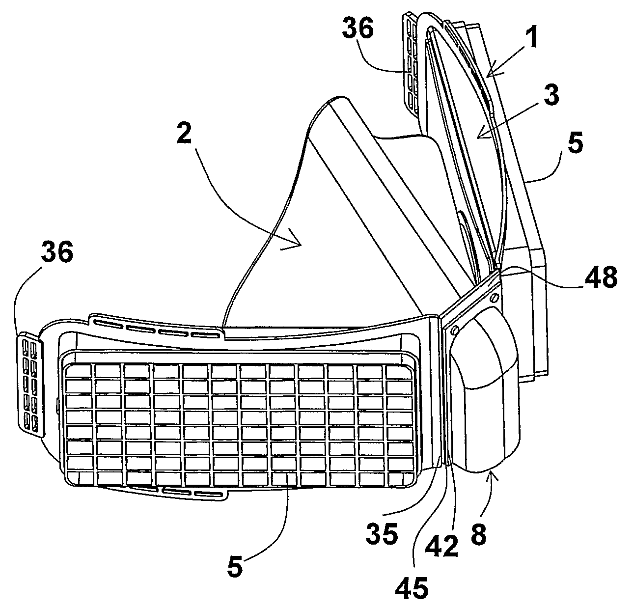
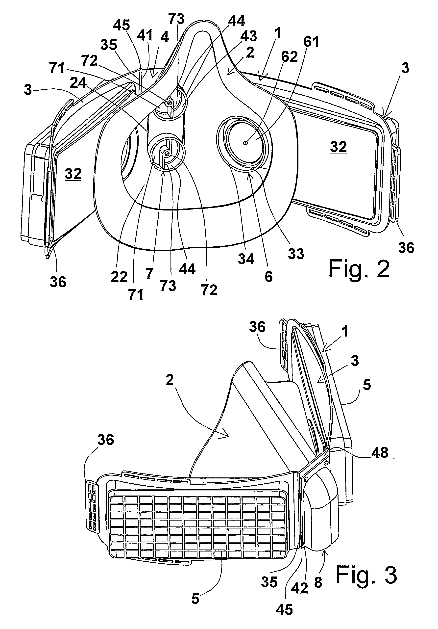
[0034]By packing the hood and air guide etc. into the space defined by the central support and the filter supports in the first position, the exterior of the respirator in its storage state may be entirely defined by the filter supports and filters. Thus, the respirator may take a neat and compact state for storage. In the storage state, the central support and filter supports act as shields for the hood and air guide etc., protecting them from damage e.g. during transit of the respirator. Preferably, the respirator in this storage state may be carried on a utility belt of the user, or stored in close proximity to the user (e.g. in a glove compartment of a car).

Problems solved by technology

These masks are often cumbersome, expensive, and must be sized to the particular wearer, in order to provide an effective seal around the periphery of the wearer's face.
These are designed to assist escape from CBRN hazards, and are not intended for prolonged or repeated use.
However, this shape is not ideal for storage on e.g. a utility belt worn by a person, as it can hinder the person's movement.
Furthermore, the oro-nasal mask is not well protected with this configuration, and may therefore be vulnerable to damage e.g. during transit.

Method used


Image

  • Respirator
  • Respirator
  • Respirator

Examples


first embodiment

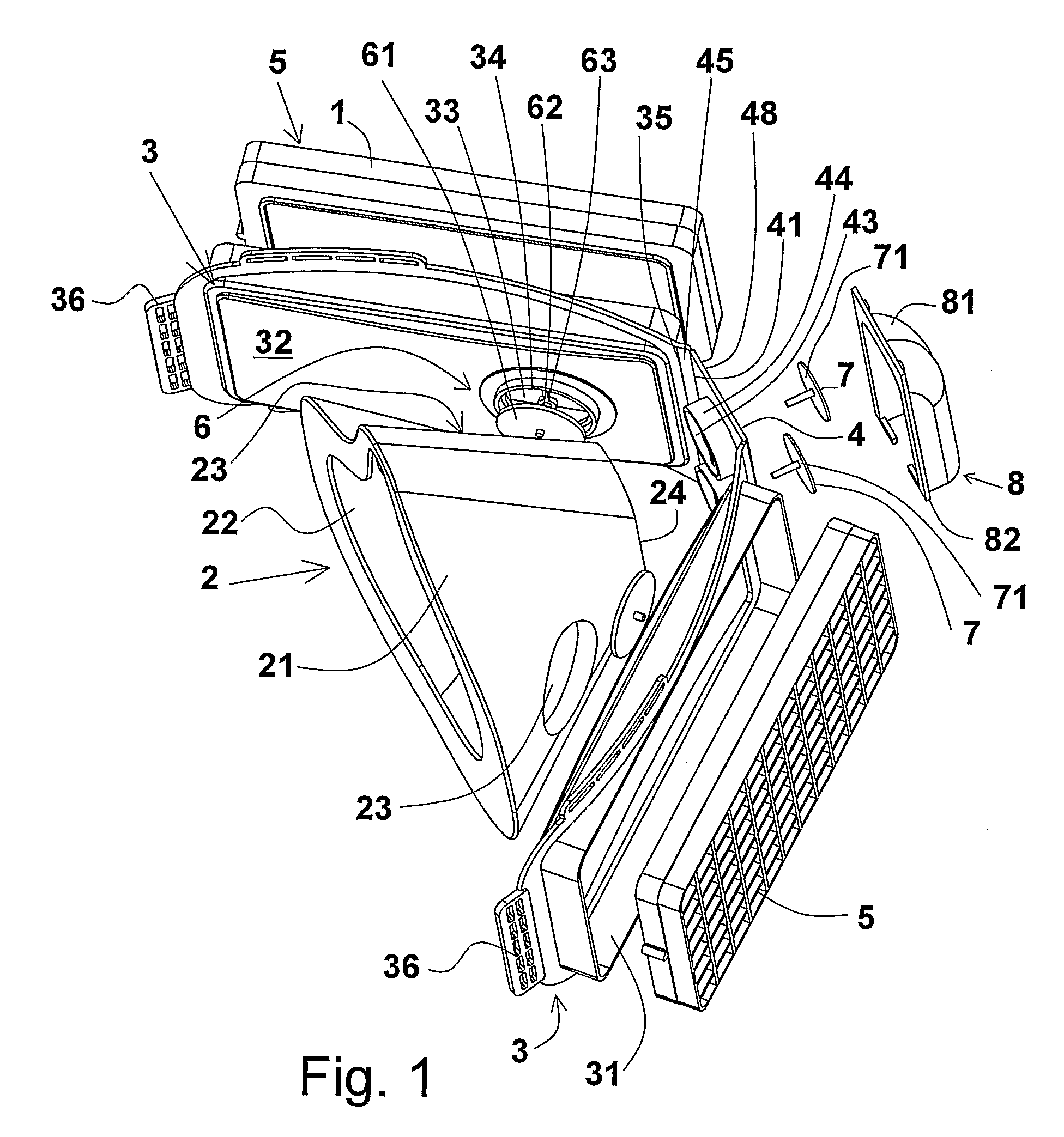
[0047]A filter section 1 and a collapsible oro-nasal mask 2 of a respirator according to the present invention is shown in FIGS. 1 to 5. The filter section 1 comprises two filter supports 3 each hinged to a central support 4. The collapsible oro-nasal mask 2 is resiliently deformable.

[0048]The filter support elements 3 provide generally rectangular sockets 31 in which correspondingly shaped filters 5 are mounted. The sockets 31 are formed on the front side of each filter supports 3. The rear side of each filter supports 3 has a generally flat rear surface 32.

[0049]The walls 21 of the oro-nasal mask 2 define an inner region 22 of the oro-nasal mask 2 within which a wearer's nostrils and mouth are located, in use. The walls 21 of the oro-nasal mask 2 are contoured in order to provide a close fit, and preferably to provide a seal with, the wearer's face (in particular the wearer's nose and chin).

[0050]A circular opening 33 is provided in each filter support, to allow air to pass throug...

second embodiment

[0061]a respirator according to the present invention is shown in FIGS. 6 to 9.

[0062]FIG. 6 shows the respirator, which includes a filter section 1′, an oro-nasal mask 2, a hood 12 and a harness 13. Parts of the respirator of the second embodiment that have the same general configuration and functionality as parts of the respirator of the first embodiment have been given the same reference numbers.

[0063]The filter section 1′ is almost identical to the filter section 1 of the first embodiment, except for the exhale valve cover 8′ of filter section 1′, which has a different shape. The front face 83 of this exhale valve cover 8′ has undulated side edges 84, which allow larger exhale valves (not shown) to be used in the respirator.

[0064]The hood 12 of the respirator can be seen best in FIG. 7. The hood 12 is of thin polyurethane material that can be folded easily, and is welded to form a self-supporting structure. Since the hood 12 can be folded easily, it may be stored in a confined en...


PUM


Abstract

A respirator which has a collapsible air guide (2) and two filter supports (3), the filter supports (3) each having a first end (35)=joined to the first end (35) of the other, and a second end (36) opposite to the first end (35). The air guide (2) is in a collapsed state when second ends (36) of the filter supports (3) are adjacent to one another, and is in a deployed state when the second ends (36) are further apart. The air guide (2) may be located between the filter supports (3) when the second ends (36) of the filter supports (3) are adjacent to each other.

Description

BACKGROUND OF THE INVENTION[0001]1. Field of the Invention[0002]This invention relates to respirators, in particular respirators intended for single emergency use.[0003]2. Summary of the Prior Art[0004]Filtration masks have been known for many years and have been developed particularly for use in military conflicts, to provide protection for e.g. soldiers against chemical and biological hazards. These masks usually employ a rubber mask section which covers the wearers face, and acts as a housing for air filters. These masks must seal effectively around the face of the wearer, to ensure that no hazardous vapours can enter the wearer's respiratory system by routes other than via the air filters. These masks are often cumbersome, expensive, and must be sized to the particular wearer, in order to provide an effective seal around the periphery of the wearer's face.[0005]Other more simple masks are known, such as surgical masks that are used by doctors and surgeons, in order to protect pa...

Claims


Application Information

Patent Timeline
IPC IPC(8): A62B23/02A62B18/10A62B7/10A62B17/04A62B18/02
CPCA62B7/10A62B18/02A62B17/04A62B25/00
Inventor HINE, JUSTINDAVIS, BRIANDURANT, MARCUS
Owner AVON POLYMER PROD LTD
Learn More