Downhole gas flow powered deliquefaction pump

a deliquefaction pump and gas flow technology, which is applied in the direction of piston pumps, borehole/well accessories, survey, etc., can solve the problems of slow gas production from the well, increased installation costs, and clearly undesirable situations

Active Publication Date: 2009-09-03
BP CORP NORTH AMERICA INC
View PDF5 Cites 35 Cited by
  • Summary
  • Abstract
  • Description
  • Claims
  • Application Information

AI Technical Summary

Benefits of technology

[0007]It has now been found that such gas removal can be readily accomplished by a method for removing liquid from a gas well comprising a wellbore extending from an earth surface to penetrate a subterranean gas-bearing formation and a casing positioned in the wellbore, the casing including perforations to permit gas to flow from the subterranean gas-bearing formation into and inside of the casing, the method consisting essentially of: sealingly positioning a packer in the casing above the perforations to sealingly close an inside of the casing; positioning a pump beneath a first liquid surface below the packer in the casing; producing electrical power with an energy recovery system by passing a gas recovered from the subterranean gas-bearing formation at a pressure greater than a pressure at the earth surface through the energy recovery system; powering the pump with the electrical power and operating the pump at a variable rate to maintain the first liquid surface below a first selected level by pumping liquid via a line through the packer to the earth surface; and, providing a liquid drain through the packer and draining liquid from above the packer to maintain a second liquid surface above the packer at a second selected level.
[0008]The invention further comprises a system for removing water from a gas well comprising a wellbore extending from an earth surface to penetrate a subterranean gas-bearing formation and a casing positioned in the wellbore, the casing including perforations to permit gas to flow from the subterranean gas-bearing formation into an inside of the casing, the system comprising: a packer adapted to sealingly close the inside of the casing above the perforations; an energy recovery system including a passageway sealingly positioned through the packer and adapted to produce electrical energy from gas flowing through the passageway; a pump positioned beneath the packer to pump liquid from the casing beneath the packer through a line sealingly positioned through the packer and in fluid communication with a pump outlet and the earth surface; an electrical connector connecting the energy recovery system and an electric motor positioned to drive the pump; a level controller positioned in operative contact with at least one of the energy recovery system and the pump motor to control the pump to maintain a selected liquid level beneath the packer; and, a drain pipe sealingly positioned through the packer, the drain pipe including a drain pipe level controller to control a liquid level above the packer.

Problems solved by technology

As the gas is produced, the liquid accumulates in the well to a height such that it may well cover the perforations through the well casing into the gas-bearing formation, thereby slowing the production of gas from the well due to the increased hydrostatic head over the outlet from the gas-bearing formation.
Such is clearly an undesirable situation.
This procedure requires additional expense for the installation of the pump and pump motor as well as expense for the electricity required to power the pump and additionally possible expensive maintenance for the pumping equipment.
Many such gas wells may be prematurely abandoned due to such expenses when compared to the value of the produced gas.
This system uses coaxially shaft-coupled turbines which do not provide the capability to run a pump at a necessary and controlled variable speed.

Method used


Image

  • Downhole gas flow powered deliquefaction pump
  • Downhole gas flow powered deliquefaction pump

Examples


Embodiment Construction

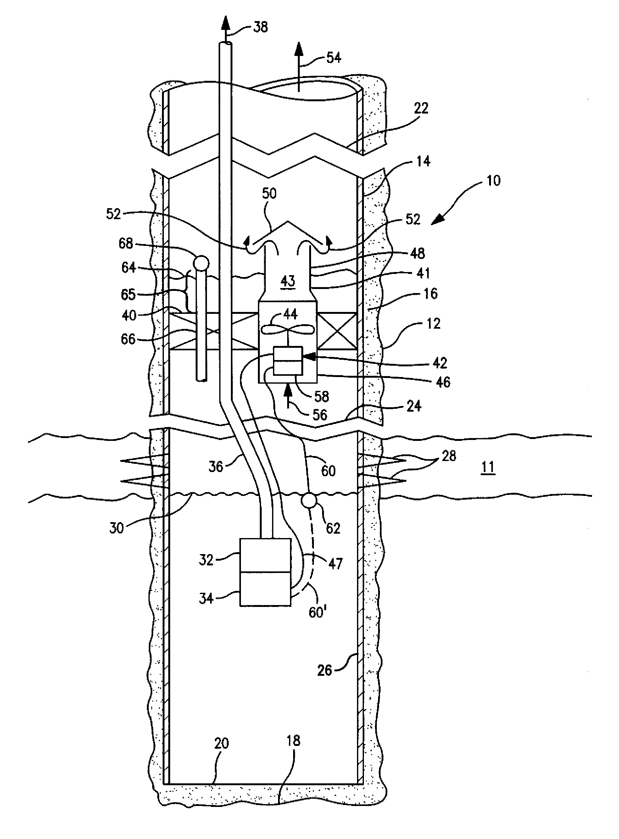
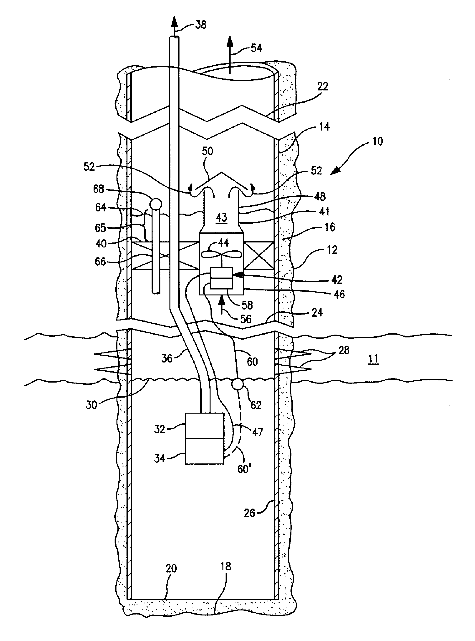
[0010]In the FIGURE, a well 10 is shown penetrating a subterranean gas-bearing formation 11 which may produce quantities of liquids, such as water, oil, mixtures of water and oil and the like. The oil may be an oleaginous substance which commonly may be referred to as oil. Well 10 comprises a wellbore 12 which includes a casing 14 cemented in place with cement 16. The well extends to a bottom 18 of wellbore 12 with the bottom 20 of the casing positioned slightly above bottom 18. Broken sections 22 and 24 indicate that the well is not to scale, especially with respect to length.

[0011]Perforations 28 are positioned to provide fluid communication between gas-bearing formation 11 and an inside 26 of casing 14. As shown, liquid has accumulated in well 10 to a level 30 beneath perforations 28 and a packer 40 which is positioned to sealingly shut-off the inside of casing 14 as shown. A pump 32 is positioned beneath liquid level 30 although pump 32 could be positioned at any level from whic...


PUM


Abstract

The present invention relates to a method and system for removing water from gas wells. The water is removed by positioning a pump in a liquid layer below the perforations through which gas enters a gas well and powering a water pump with electrical power generated by an energy recovery system which produces electricity from a gas flow through the energy recovery system to an earth surface.

Description

RELATED APPLICATIONS[0001]This invention is entitled to and hereby claims the benefit of the filing date of U.S. provisional patent application 61 / 067,774 entitled “Downhole Gas Flow Powered Deliquefaction Pump” filed Feb. 29, 2008 by Bryan D. Dotson.FIELD OF THE INVENTION[0002]The present invention relates to a method and system for removing water from gas wells. The water is removed by positioning a pump in a liquid layer below the perforations through which gas enters the gas well and powering a liquid pump with electrical power generated by an energy recovery system which produces electricity from a gas flow through the energy recovery system to an earth surface.BACKGROUND OF THE INVENTION[0003]Many wells which primarily produce gas are also prone to produce liquid in varying quantities with the produced gas. As the gas is produced, the liquid accumulates in the well to a height such that it may well cover the perforations through the well casing into the gas-bearing formation, ...

Claims


Application Information

Patent Timeline
Patent Type & Authority Applications(United States)
IPC IPC(8): E21B43/12E21B43/00
CPCE21B41/0085E21B43/128E21B43/121E21B43/13
Inventor DOTSON, BRYAN D.
Owner BP CORP NORTH AMERICA INC
Why Eureka
Try Eureka