

Fluid pressure control device
a control device and fluid pressure technology, applied in the direction of brake components, brake systems, vehicle components, etc., can solve the problems that the total brake force cannot achieve the requirements of the driver of the vehicle, and the stopping distance accordingly becomes longer
- Summary
- Abstract
- Description
- Claims
- Application Information
AI Technical Summary
Benefits of technology
Problems solved by technology
Method used
Image

Examples
first embodiment
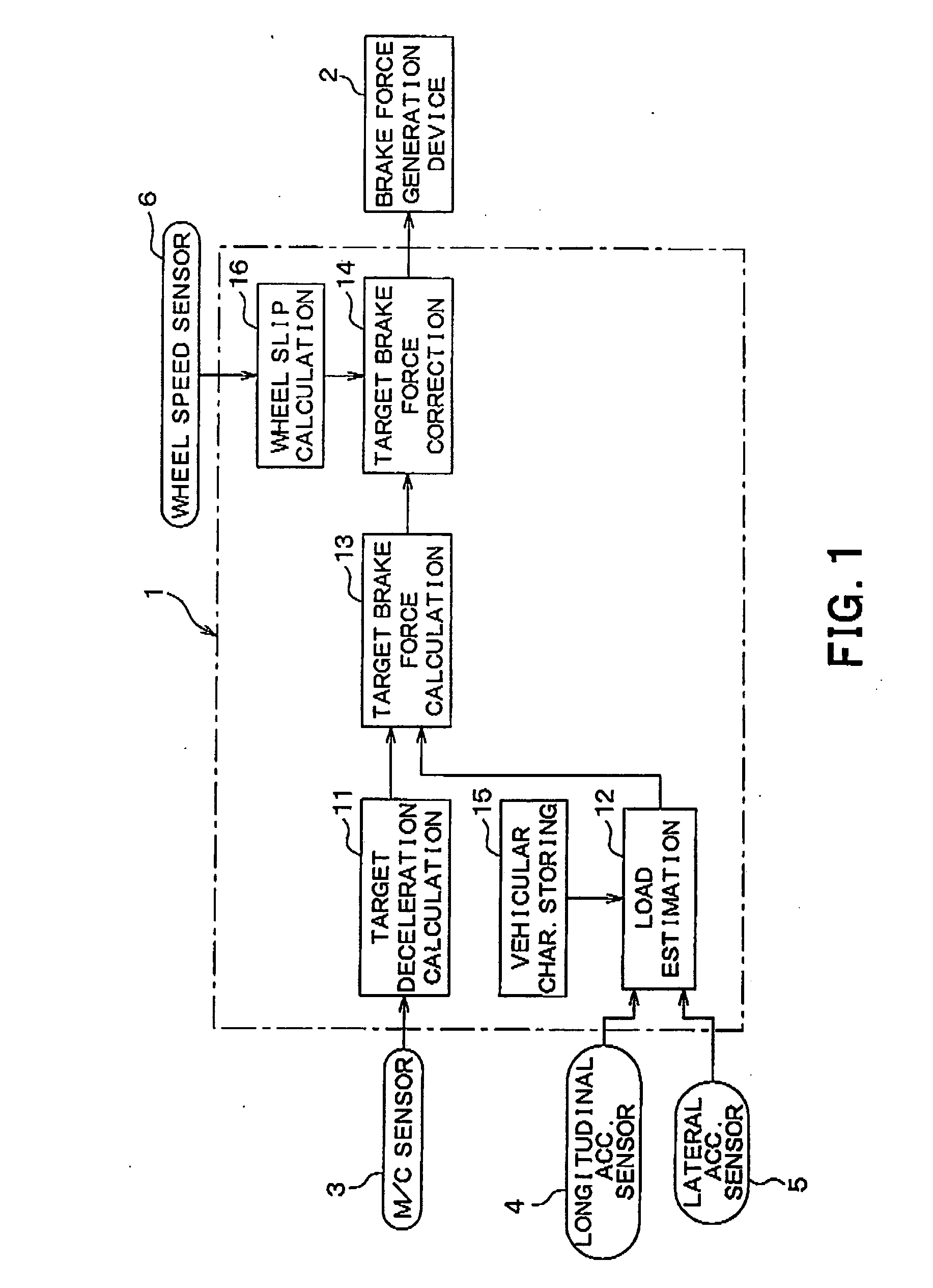
[0045]Hereinafter, a first embodiment is described. FIG. 1 is a block diagram showing a brake force distribution control device 1 for a vehicle according to the present invention. Components of the brake force distribution control device 1 are described with reference to FIG. 1.
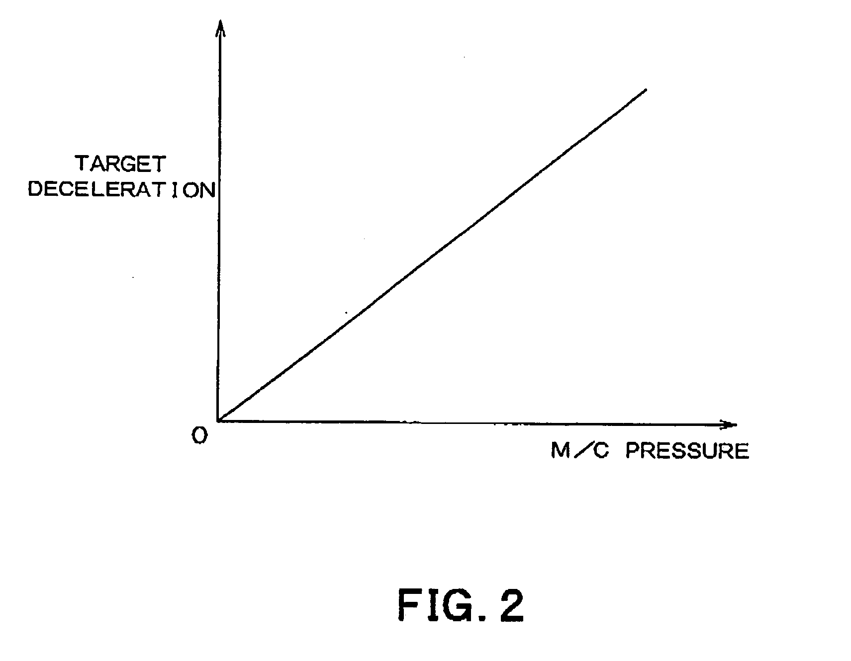
[0046]The brake force distribution control device 1 according to the present embodiment calculates target brake forces respectively for the wheels of the vehicle based on quantities detected by several sensors. Then the brake force distribution control device 1 corrects the target brake forces and transmits the corrected target brake forces to a brake force generation device 2 for the wheels. The brake force distribution control device 1 thereby causes brake force generation device 2 to generate actual brake forces respectively at the wheels of the vehicle so that the actual brake forces match the corrected target brake forces. An electric control unit (hereinafter referred to as an ECU) for use in braking is...
second embodiment
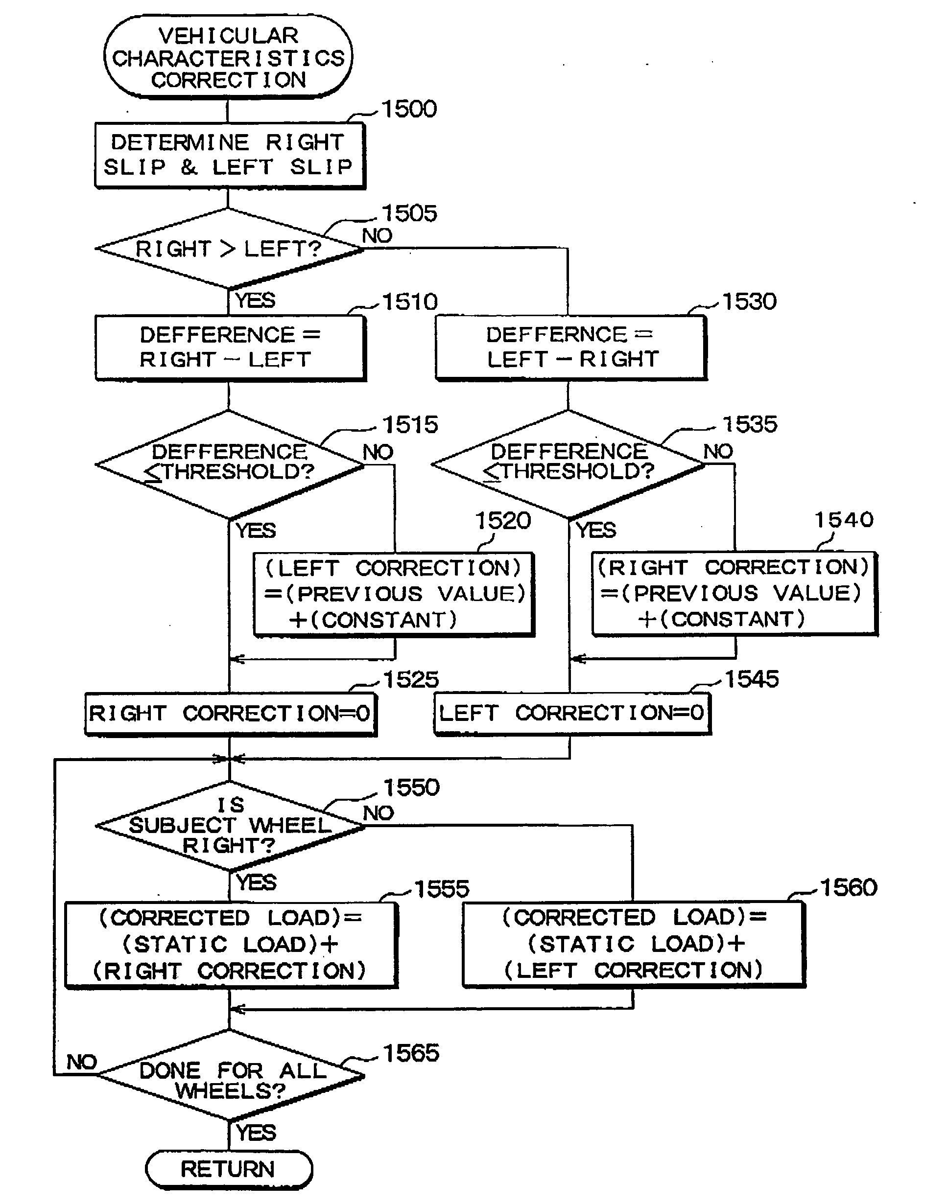
[0070]Hereinafter, a second embodiment of the present invention is described. In the present embodiment, following modification is given to the first embodiment. In the modification, the wheels of the vehicle are divided into two wheel groups, namely, a right wheel group and a left wheel group. The right wheel group includes the two right side wheels, and the left wheel group includes the two left side wheels. In the target brake force correction process in the present embodiment, the slip amount of a wheel is compared only with the slip amount of the other wheel in the same wheel group. The target brake force correction amount for a wheel is therefore determined based not on the relation with the wheels in the different wheel group but on the relation with the other wheel in the same wheel group. It should be noted that a basic configuration of the brake force distribution control device 1 according to the present embodiment is identical with that of the first embodiment. The only ...
third embodiment
[0077]Hereinafter, a third embodiment of the present invention is described. In the present embodiment, following modification is given to the first embodiment. In the modification, the wheels of the vehicle are divided into two wheel groups, namely, a front wheel group and a rear wheel group. The front wheel group includes the two front part wheels, and the rear wheel group includes the two rear part wheels. In the target brake force correction process in the present embodiment, the slip amount of a wheel is compared only with the slip amount of the other wheel in the same wheel group. The target brake force correction amount for a wheel is therefore determined based not on the relation with the wheels in the different wheel group but on the relation with other wheel in the same wheel group. It should be noted that a basic configuration of the brake force distribution control device 1 according to the present embodiment is identical with that of the first embodiment. The only diffe...
PUM
 Abstract
Description
Claims
Application Information