
Ink cartridge-attaching device and ink jet recording apparatus

a technology of ink jet recording apparatus and ink cartridge, which is applied in the direction of electrical equipment, semiconductor devices, printing, etc., can solve the problems of deterioration of light-emitting diodes, difficulty in correctly determining whether or not a state of light-emitting diodes is the state of light-emitting diodes, and difficulty in correcting the degradation of optical sensors

Active Publication Date: 2009-09-03
BROTHER KOGYO KK
View PDF9 Cites 28 Cited by
  • Summary
  • Abstract
  • Description
  • Claims
  • Application Information

AI Technical Summary

Benefits of technology

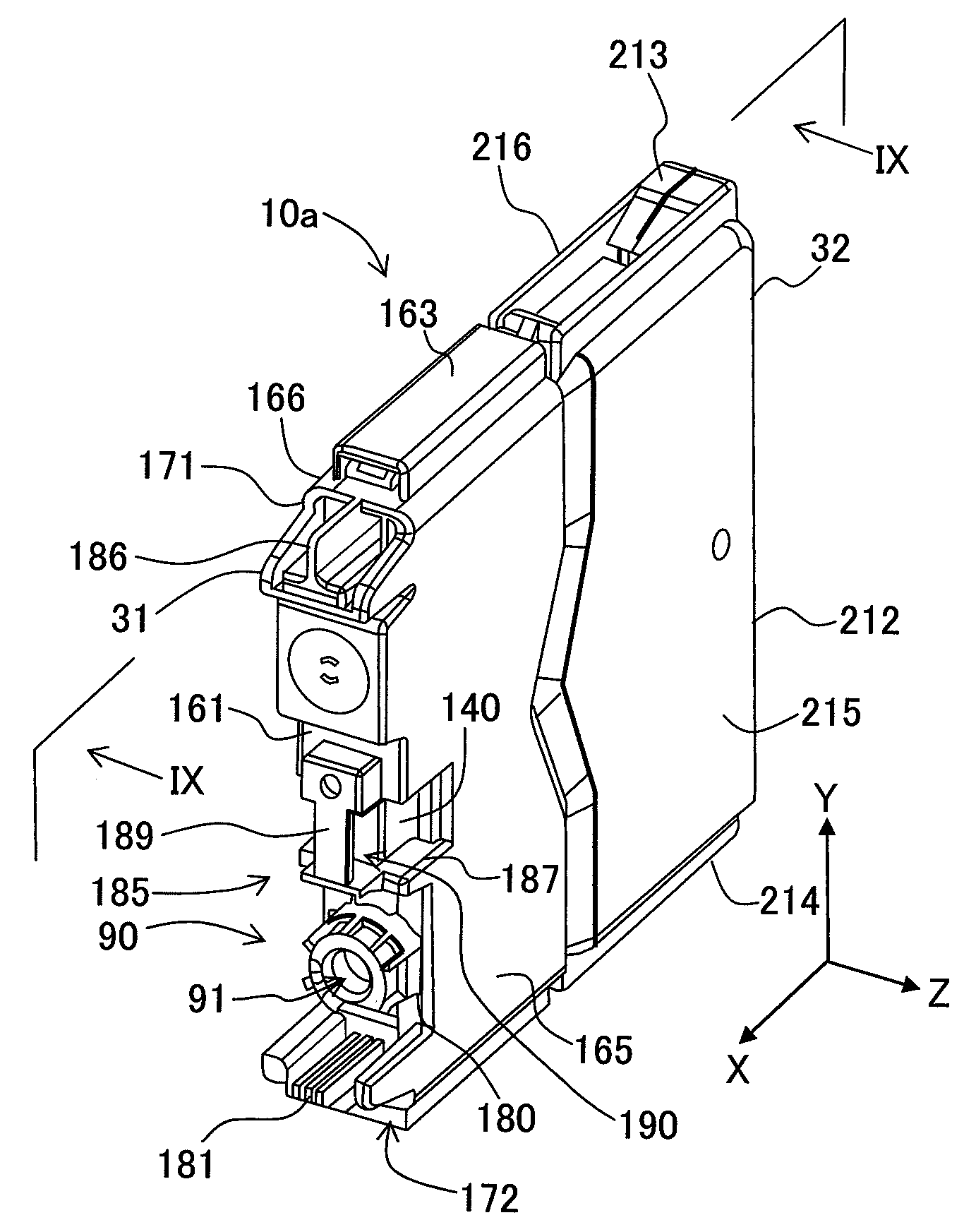
[0008]An object of the invention is to provide an ink cartridge-attaching device capable of correctly detecting the degradation of an optical sensor, which detects information about a cartridge, even in a state that the cartridge is attached to the cartridge attachment section and an ink-jet recording apparatus.

Problems solved by technology

In particular, the light-emitting diode has a characteristic that the light-emitting diode is deteriorated as the operating time passes such that illuminance or brightness of the light-emitting diode during the operation is lowered.
However, in the cartridge as described above having the detection-objective portion which shields the light from the light-emitter when the ink remaining amount is not less than the predetermined amount, it is difficult to correctly determine whether or not a state that the light-receiver does not receive a light having a predetermined luminance is due to the ink remaining amount being not less than the predetermined amount or due to the lowering of illuminance caused by the degradation of the light-emitter.

Method used


Image

  • Ink cartridge-attaching device and ink jet recording apparatus
  • Ink cartridge-attaching device and ink jet recording apparatus
  • Ink cartridge-attaching device and ink jet recording apparatus

Examples


Embodiment Construction

[0037]In the following, an explanation will be given about an ink cartridge-attaching device according to an embodiment of the present invention, as exemplified by an ink-jet recording apparatus (hereinafter referred to as “recording apparatus”) provided with the ink cartridge-attaching device, with reference to the drawings.

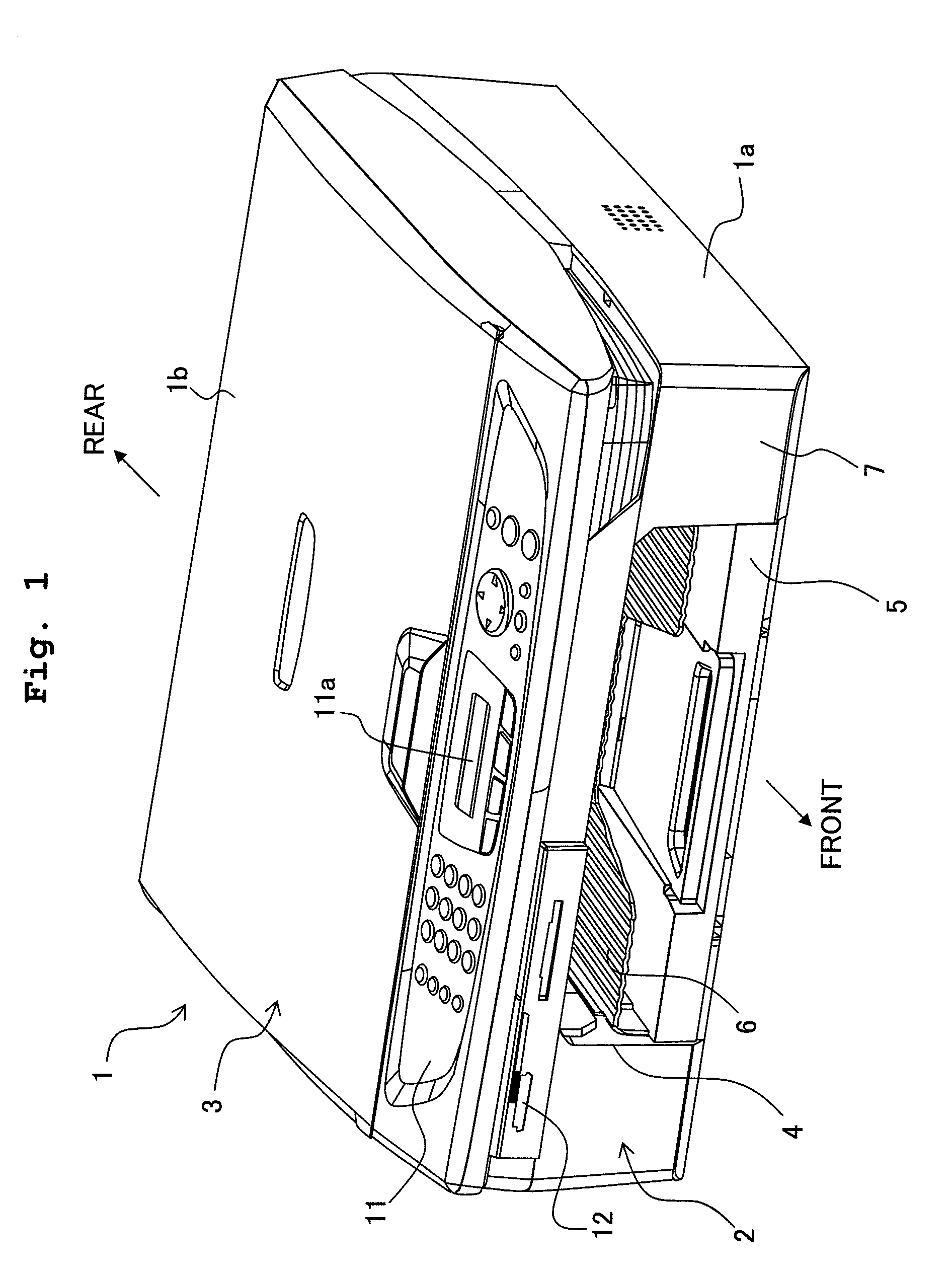
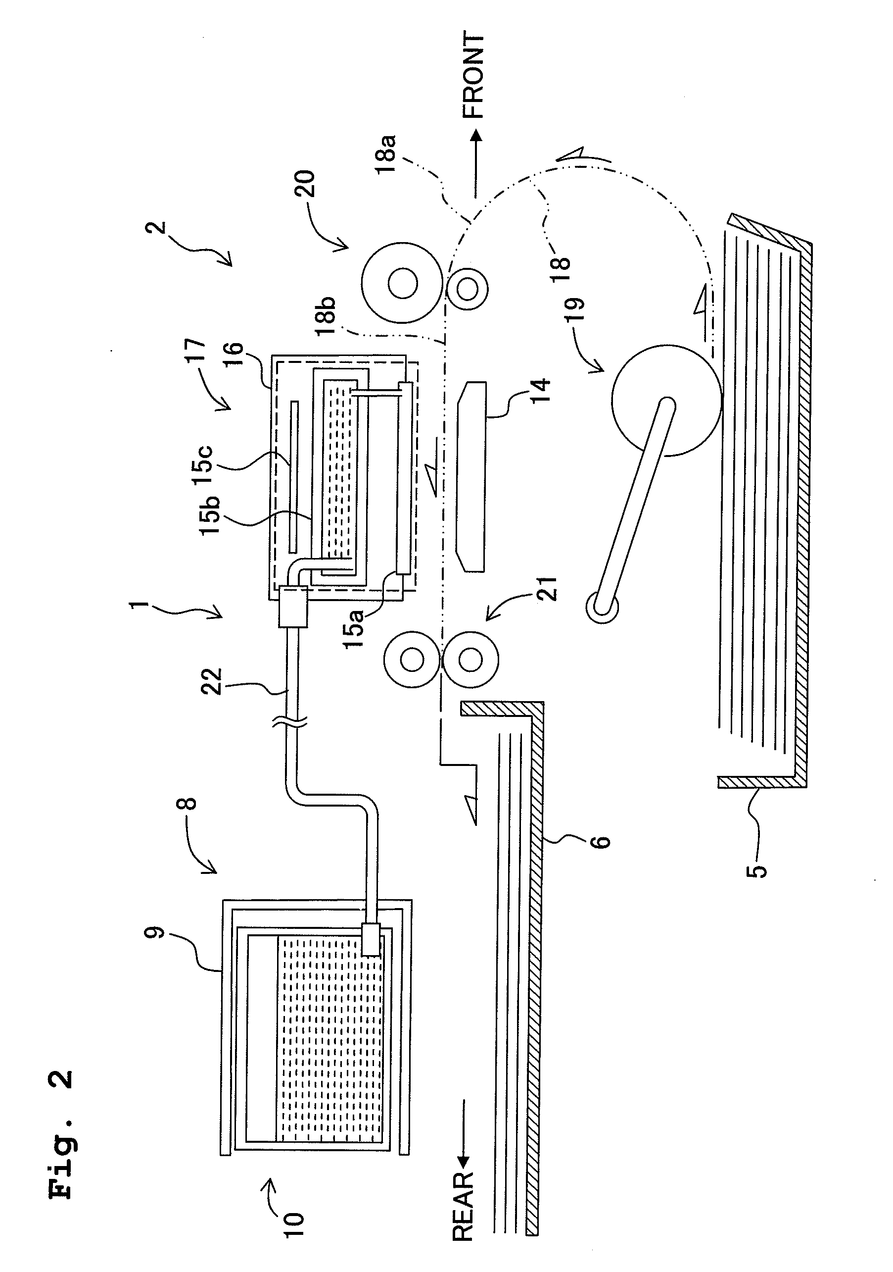
[0038]FIG. 1 is a perspective view of the external construction of a recording apparatus 1 to which the present invention is applied, and shows a so-called multi-function apparatus having a printing function, a scanning function, a copying function, a facsimile function, etc. as an embodiment of the recording apparatus 1. As shown in FIG. 1, the recording apparatus 1 is constructed to include: a casing 1a having a substantially rectangular parallelepiped shape; a printing section 2 of an ink-jet type which records an image and / or a letter on a recording paper as a recording medium and which is arranged at a lower portion of the casing 1a; and a scanning section ...


PUM


Abstract

An ink cartridge-attaching device includes a cartridge attachment section to which cartridges each storing an ink are attachable; optical sensors which are provided on the cartridge attachment section, which detect the cartridges attached to the cartridge attachment section, and each of which has light-emitting portion and light-receiving portion; and a controller which controls the optical sensors to obtain, based on signals from the optical sensors, information about the cartridges; and the optical sensors are disposed such that the light-emitting portion and the light-receiving portion of the optical sensors are arranged alternately in a row; and light emitted from the light-emitting portion included in a certain optical sensor among the optical sensors is received by the light-receiving portion included in the certain optical sensor and received by another light-receiving portion adjacent to the light-emitting portion and included in another optical sensor, among the optical sensors, adjacent to the certain optical sensor.

Description

CROSS REFERENCE TO RELATED APPLICATION[0001]The present application claims priority from Japanese Patent Application No. 2008-051992, which was filed on Mar. 3, 2008, the disclosure of which is herein incorporated by reference in its entirety.BACKGROUND OF THE INVENTION[0002]1. Field of the Invention[0003]The present invention relates to an ink cartridge-attaching device capable of detecting degradation of an optical sensor which detects a cartridge attached to a cartridge attachment section.[0004]2. Description of the Related Art[0005]Conventionally, there are widely known ink-jet recording apparatuses each of which records an image and / or a letter on a recording paper by jetting ink from a recording head onto the recording paper. A cartridge storing the ink can be attached to the recording apparatus, and the ink supplied from the cartridge is jetted from the recording head. In a case that a remaining amount of the ink remaining in the cartridge (ink remaining amount) becomes relat...

Claims


Application Information

Patent Timeline
IPC IPC(8): B41J2/195
CPCB41J2002/17573B41J2/17566
Inventor KONDO, HIROFUMI
Owner BROTHER KOGYO KK
Learn More