Method of creating particle size distribution model, method of predicting degradation of fuel cell catalyst using the method of creating particle size distribution model, and method of controlling fuel cell using the method of predicting degradation of fuel cell catalyst

a technology of particle size distribution model and particle size distribution model, which is applied in the direction of cell components, instruments, electrochemical generators, etc., can solve the problems of not always obtaining precise simulation results that agree with experimental results, voltage reduction, etc., and achieve the effect of improving precision and reducing calculation tim

Active Publication Date: 2014-02-25
TOYOTA JIDOSHA KK
View PDF13 Cites 0 Cited by
  • Summary
  • Abstract
  • Description
  • Claims
  • Application Information

AI Technical Summary

Benefits of technology

[0011]The invention provides a method of creating a particle size distribution model with improved preciseness, within a shortened calculation time, a method of predicting degradation of a fuel cell catalyst, using the method of creating the particle size distribution model, and a method of controlling a fuel cell, using the method of predicting degradation of the fuel cell catalyst.
[0015]According to the method of predicting degradation of the fuel cell catalyst as described above in which the above-described particle size distribution model creating method is used for prediction of degradation of the fuel cell catalyst, degradation of the fuel cell catalyst which is more likely to occur in reality can be precisely simulated within the same calculation lime, as compared with the case where the particle size distribution model of the related art is used for prediction of degradation of the fuel cell catalyst. Also, according to the method of predicting degradation of the fuel cell catalyst of the invention in which the above-described particle size distribution model creating method is used for prediction of degradation of the fuel cell catalyst, it is possible to provide results having the same or equivalent preciseness as results obtained when the particle size distribution model of the related art is used for prediction of degradation of the fuel cell catalyst, within a shorter time than that required in the related art.
[0017]According to the present invention, the particle size distribution is determined, using the minimum particle size, the maximum particle size, and the respective points at which the integral of the frequency of appearance is equally or evenly divided, as typical points. It is thus possible to create a particle size distribution model that can precisely simulate a particle size distribution obtained by experiment, with a reduced number of variables, as compared with the particle size distribution model of the related art.

Problems solved by technology

One of the problems encountered in the polymer electrolyte fuel cell is voltage reduction caused by dissolution of catalyst metal in the electrodes.
However, even if the mathematical model described in this document is used, precise simulation results that agree with experimental results are not necessarily obtained, as is apparent from FIG. 1 and FIG. 5 of this document.

Method used


Image

  • Method of creating particle size distribution model, method of predicting degradation of fuel cell catalyst using the method of creating particle size distribution model, and method of controlling fuel cell using the method of predicting degradation of fuel cell catalyst
  • Method of creating particle size distribution model, method of predicting degradation of fuel cell catalyst using the method of creating particle size distribution model, and method of controlling fuel cell using the method of predicting degradation of fuel cell catalyst
  • Method of creating particle size distribution model, method of predicting degradation of fuel cell catalyst using the method of creating particle size distribution model, and method of controlling fuel cell using the method of predicting degradation of fuel cell catalyst

Examples


Embodiment Construction

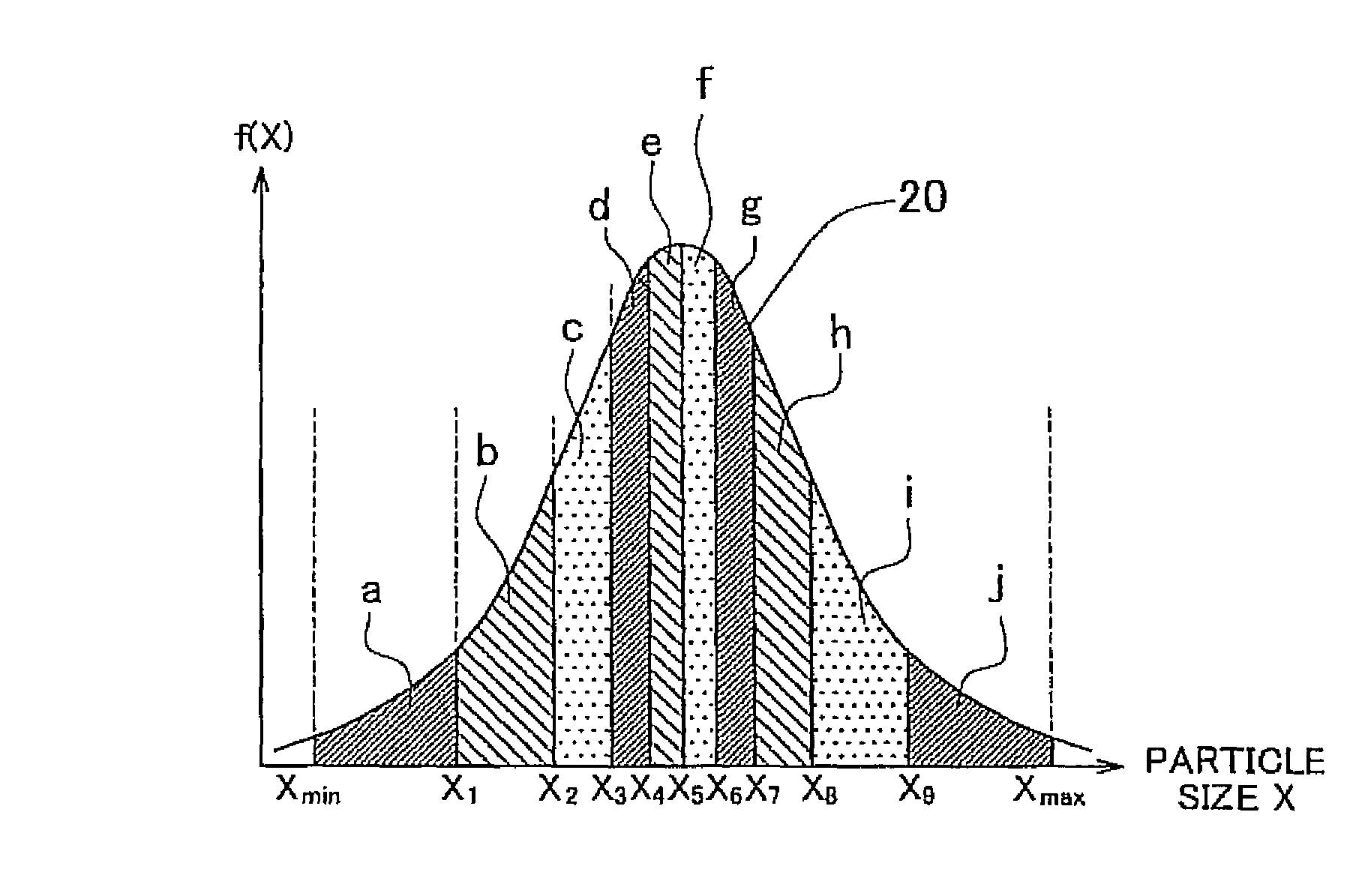
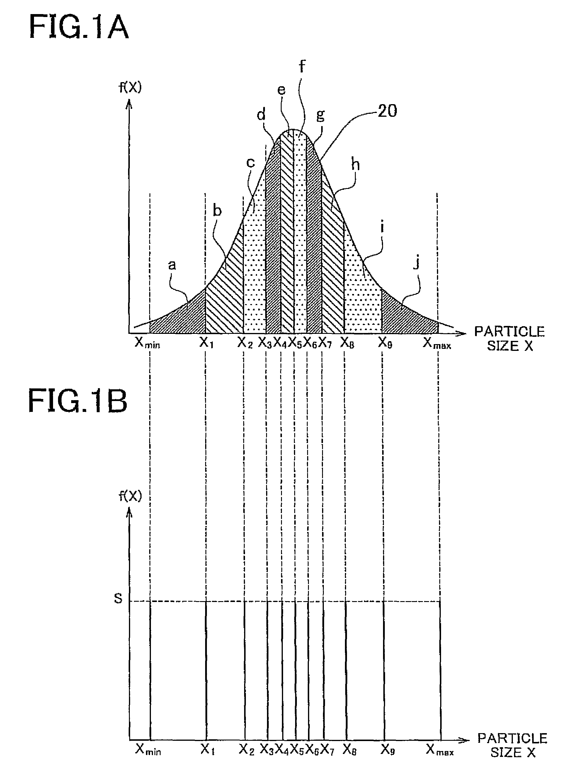
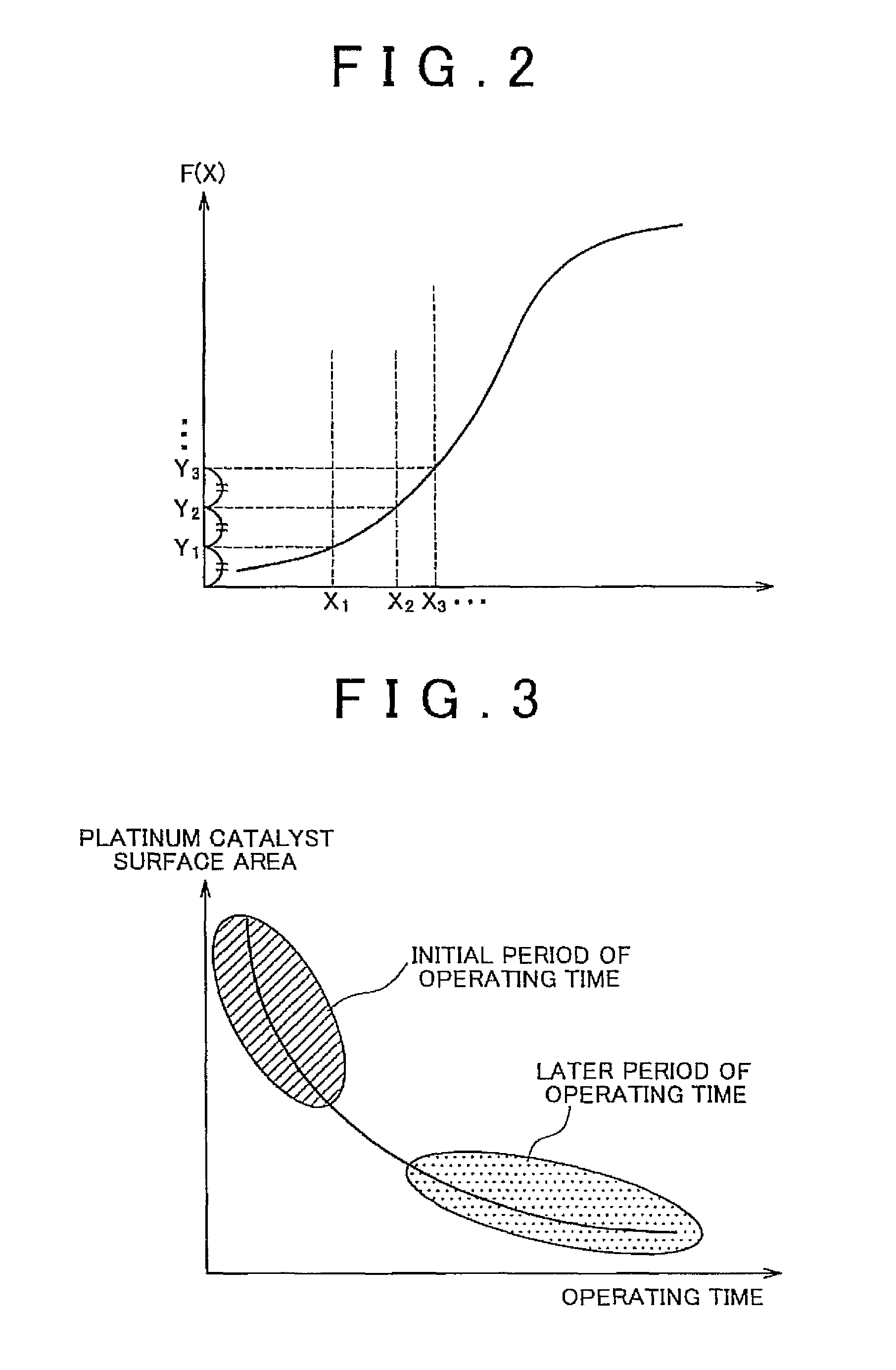
[0028]A particle size distribution model creating method of the invention, which is a method of creating a particle size distribution model that simulates a particle size distribution of a cluster of particles as a collection of a plurality of particles having different particle sizes, includes a particle size range determining step of determining the minimum particle size and maximum particle size of the particles included in the cluster of particles to be simulated, an integrating step of integrating the frequency of appearance of the particles within the particle size range determined in the particle size range determining step, over an integration region defined by the minimum particle size as a starting point and the maximum particle size as an endpoint, a division point determining step of dividing the integration region used in the integrating step into a given number of regions through a first dividing operation, using the integral of the frequency of appearance obtained in ...


PUM


Abstract

A particle size distribution creating method includes a particle size range determining step, an integrating step of integrating the frequency of appearance of particles within the particle size range determined in the particle size range determining step, a division point determining step of determining particle sizes that provide division points, using the integral of the frequency of appearance obtained in the integrating step, and a typical point determining step of determining the minimum particle size, maximum particle size and the particle sizes of the division points as typical points. This method is characterized by assuming a particle size distribution which contains particles having the particle sizes of the respective typical points and is plotted such that the frequency of appearance of the particles having the particle size of each of the typical points is equal to the integral over each of the regions defined by the typical points, and obtaining the assumed particle size distribution as a particle size distribution model.

Description

INCORPORATION BY REFERENCE[0001]The disclosure of Japanese Patent Application No. 2009-084428 filed on Mar. 31, 2009 including the specification, drawings and abstract is incorporated herein by reference in its entirety.BACKGROUND OF THE INVENTION[0002]1. Field of the Invention[0003]The invention relates to a method of creating a particle size distribution model, a method of predicting degradation of a fuel cell catalyst, using the method of creating the particle size distribution model, and a method of controlling a fuel cell, using the method of predicting degradation of the fuel cell catalyst.[0004]2. Description of the Related Art[0005]Fuel cells are operable to convert chemical energy directly into electrical energy, by supplying fuel and an oxidizing agent to two electrodes that are electrically connected, and electrochemically causing oxidation of the fuel. Unlike thermal power generation, fuel cells are free from constraints of the Carnot cycle, and thus exhibit a high energ...

Claims


Application Information

Patent Timeline
Patent Type & Authority Patents(United States)
IPC IPC(8): G06G7/48
CPCY02E60/50H01M4/90H01M2008/1095G01N15/0266G06F19/70H01M4/9041G06F17/5009H01M8/04992G01D21/00G06F15/00G06F17/10H01M8/04119G16C99/00G06F30/20
Inventor KIMURA, HIROKOTAKEHIRO, NAOKIKATO, MANABUKIMURA, KAZUTAKA
Owner TOYOTA JIDOSHA KK
Why Eureka
Try Eureka