Transcriber and image forming apparatus including the same
a technology of image forming apparatus and transcriber, which is applied in the direction of electrographic process apparatus, instruments, optics, etc., can solve the problems of reducing the preciseness of the superimposed toner images of the different colors, reducing the accuracy of the superimposed toner images, and reducing the quality of the image to be secondarily transferred to the sheet, so as to achieve the effect of suppressing the precise degradation of image formation and improving the accuracy of image formation
- Summary
- Abstract
- Description
- Claims
- Application Information
AI Technical Summary
Benefits of technology
Problems solved by technology
Method used
Image
Examples
embodiment 1
[0028]Image Forming Apparatus
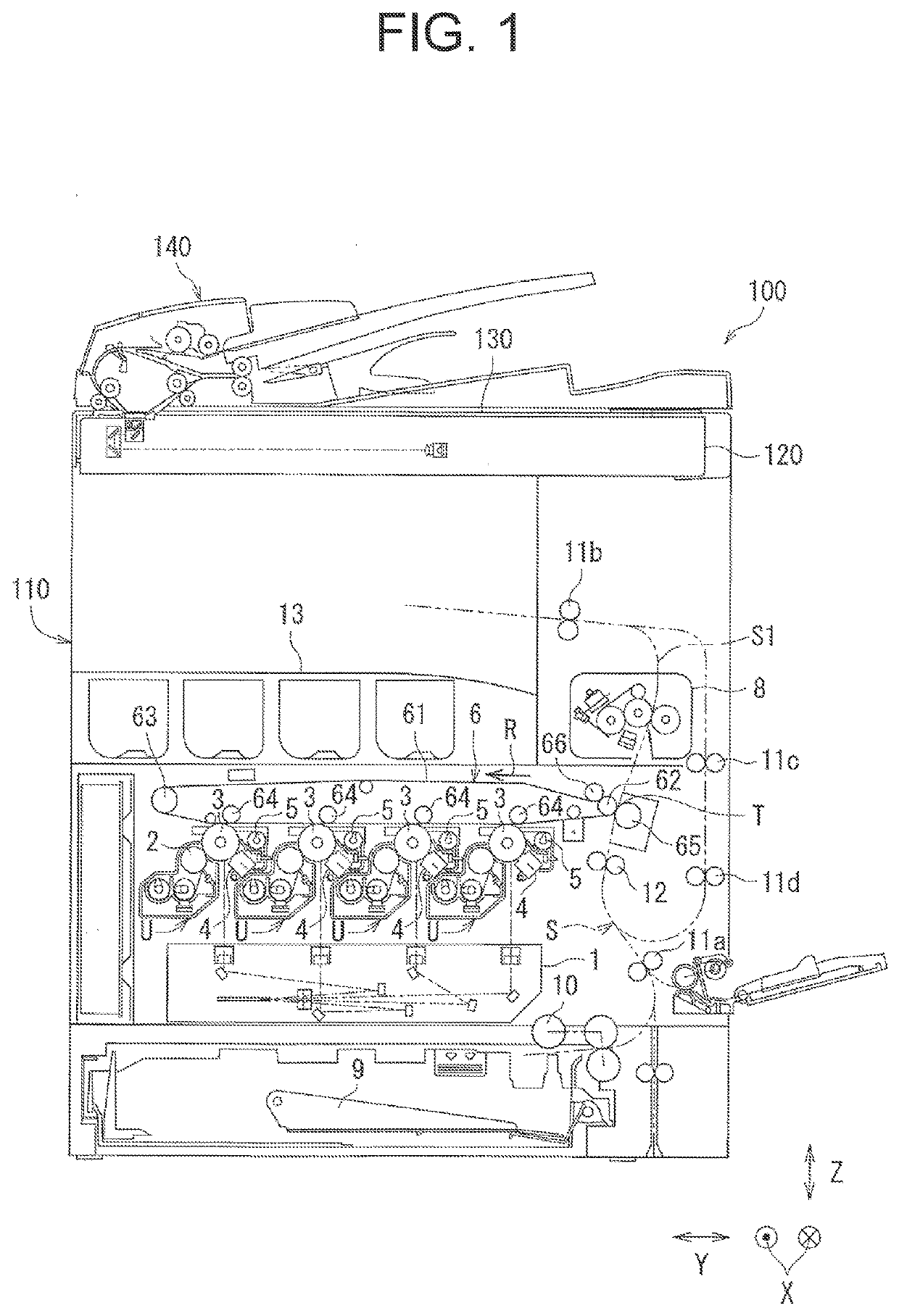
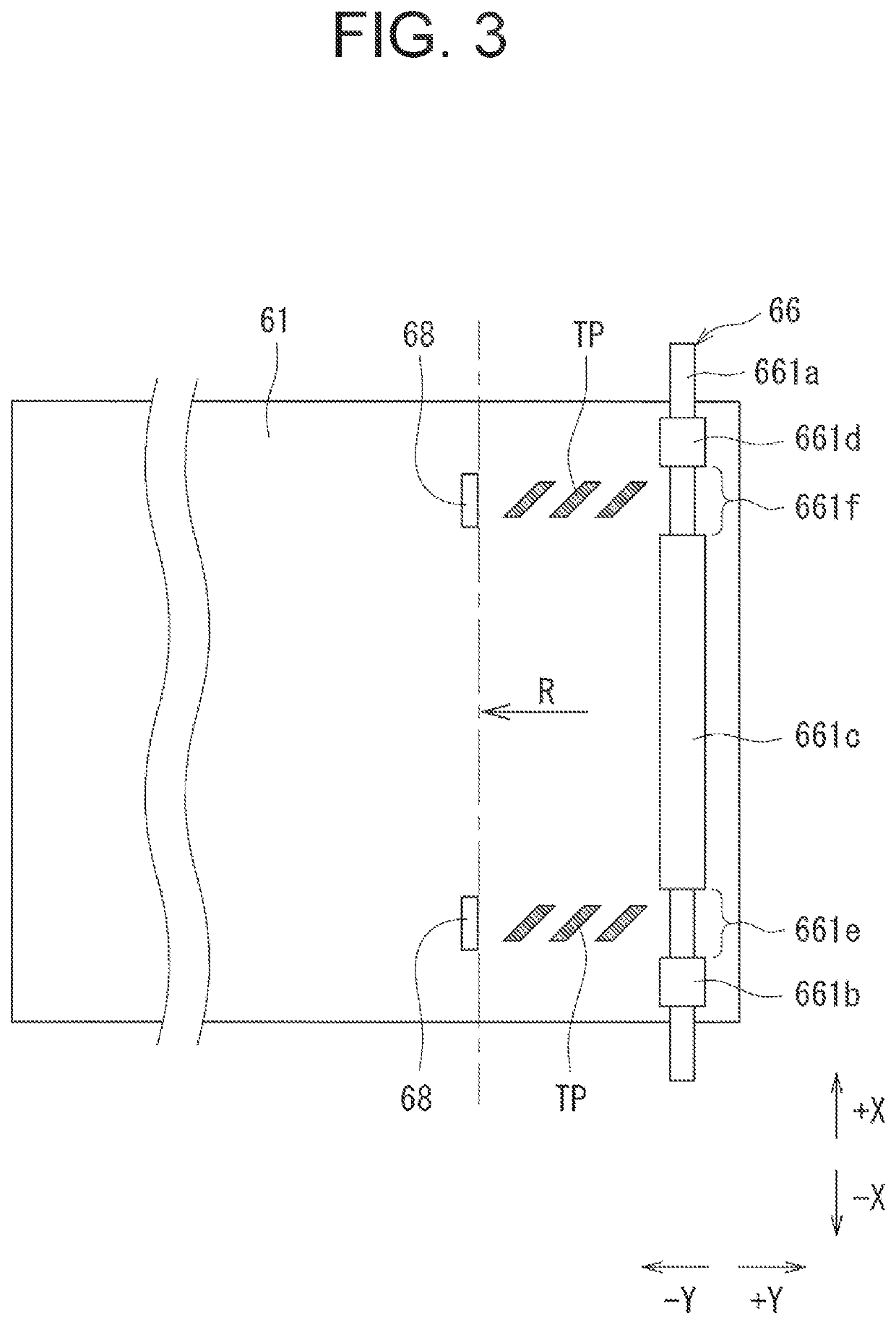
[0029]FIG. 1 is a schematic cross-sectional view illustrating a configuration of an image forming apparatus 100 according to an embodiment 1. In the drawings, a reference character X indicates a width direction a depth direction), in which a −X direction (i.e., a minus X direction) defines a front direction and a +X direction (i.e., a plus X direction) defines the rear direction. The reference character Y indicates a left and right direction orthogonal to the width direction X, in which a −Y direction (i.e., a minus Y direction) defines a left direction and a +Y direction (i.e., a plus Y direction) defines the right direction. The reference character Z indicates an up and down direction, in which a −Z direction (i.e., a minus Z direction) defines a downward direction and a +Z direction (i.e., a plus Z direction) defines the upward direction.
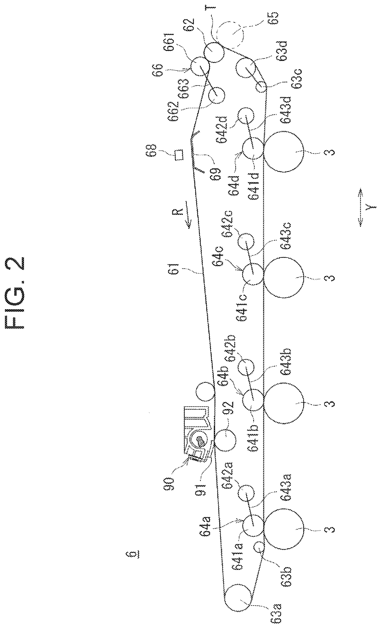
[0030]A body 110 of the image forming apparatus 100 includes an exposure device 1, a developing device 2, an image ...
second embodiment
[0116]FIG. 8 is a schematic front view illustrating a portion of a configuration of the transcriber 6 according to a second embodiment.
[0117]In the second embodiment, when the belt presser 66 is pressed against the intermediate transfer belt 61, the belt presser 66 abuts on the driving roller 62 via the intermediate transfer belt 61 (see FIG. 8). By pressing the belt presser 66, the intermediate transfer belt 61 is sandwiched between the belt presser 66 and the driving roller 62. As a result, a stable contact between the belt presser 66 and the intermediate transfer belt 61 can be achieved, it results in an effect that the slippage of the intermediate transfer belt 61 can be effectively suppressed.
[0118]Furthermore, in the second embodiment, the belt presser 66 is pressed against the intermediate transfer belt 61 so as to direct toward the driving roller 62 (see FIG. 8). An orientation of normal force generated on the driving roller 62 by pressing the belt presser 66 to the driving ...
third embodiment
[0119]FIG. 9 is a schematic front view illustrating a portion of a configuration of the transcriber 6 according to a third embodiment.
[0120]In the third embodiment, the belt presser 66 is pressed against the intermediate transfer belt 61 on the downstream side from the contact area in which the intermediate transfer belt 61 and the driving roller 62 are in contact with each other in the circulation direction of the intermediate transfer belt 61 (see FIG. 9). Thereby, it results in an effect that a degree of freedom of a layout design is improved, since the belt presser 66 can be provided even when it is spatially difficult to locate the belt presser 66 in the vicinity of the driving roller 62.
PUM
 Abstract
Description
Claims
Application Information
 - R&D
- Intellectual Property
- Life Sciences
- Materials
- Tech Scout
- Unparalleled Data Quality
- Higher Quality Content
- 60% Fewer Hallucinations
Browse by: Latest US Patents, China's latest patents, Technical Efficacy Thesaurus, Application Domain, Technology Topic, Popular Technical Reports.
© 2025 PatSnap. All rights reserved.Legal|Privacy policy|Modern Slavery Act Transparency Statement|Sitemap|About US| Contact US: help@patsnap.com


