Lighting apparatus

a technology of lighting apparatus and lighting support device, which is applied in the direction of lighting and heating apparatus, fixed installation, etc., can solve the problem of not being able to give a gorgeous stage effect of illumination, and achieve the effect of good stage effect, good atmosphere and beautiful interior design

Inactive Publication Date: 2009-09-03
YAMAGATA PROMOTIONAL ORG FOR INDAL TECH
View PDF10 Cites 4 Cited by
  • Summary
  • Abstract
  • Description
  • Claims
  • Application Information

AI Technical Summary

Benefits of technology

[0014]According to the above-mentioned lighting apparatus, the planar frames having mounted thereon the plane light emitter are connected mutually and annularly so that the light emitting units of one ring are arranged, and a plurality of light emitting units of other rings are similarly arranged and formed concentrically, so to speak. Therefore, a stainless steel plate may be used for the planar frames which constitute the light emitting units of each of the above-mentioned rings, and subjected to decoration processing, such as for example hairline processing etc., so that the lighting apparatus can be provided having a high-class feeling and a stately feeling, or having an appearance like a chandelier, so to speak.
[0015]In addition, a mounting side of the plane light emitter in each frame is arranged to form a dome shape, so that a cubic effect can be obtained further and it is possible to realize the lighting apparatus which can aim at giving a gorgeous interior design, a good stage effect, and a good atmosphere.
[0016]Further, it is possible to realize the lighting apparatus in which an organic EL element can be used as a plane light emitter to be mounted to each of the above-mentioned frames, a high luminous efficiency can be obtained by means of a low-voltage drive power source without heat generation, and an excellent decoration effect can be obtained as compared with an image of the lighting apparatus using a conventional fluorescent light, an electric bulb, etc.

Problems solved by technology

However, in the above-mentioned lighting apparatus, it only suggests that a luminescence pattern in a flat luminescence surface is devised, and it has no distinctions, lacks a cubic effect, and remains monotonous in the devised range of the above-mentioned luminescence pattern.
Therefore, it is impossible to allow the illumination to give a gorgeous stage effect etc.

Method used


Image

  • Lighting apparatus
  • Lighting apparatus
  • Lighting apparatus

Examples


Embodiment Construction

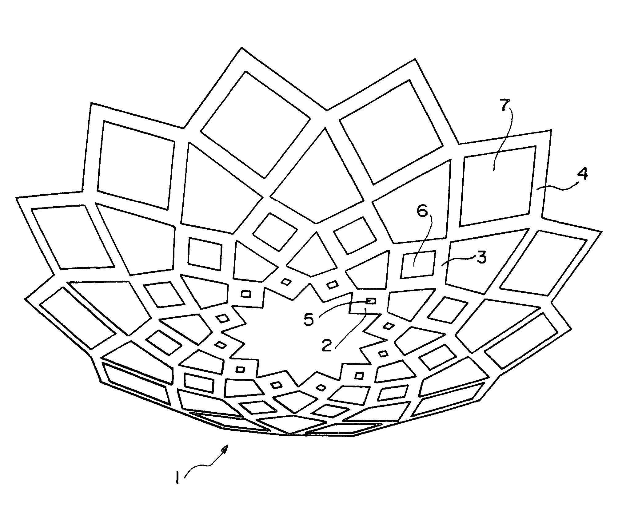
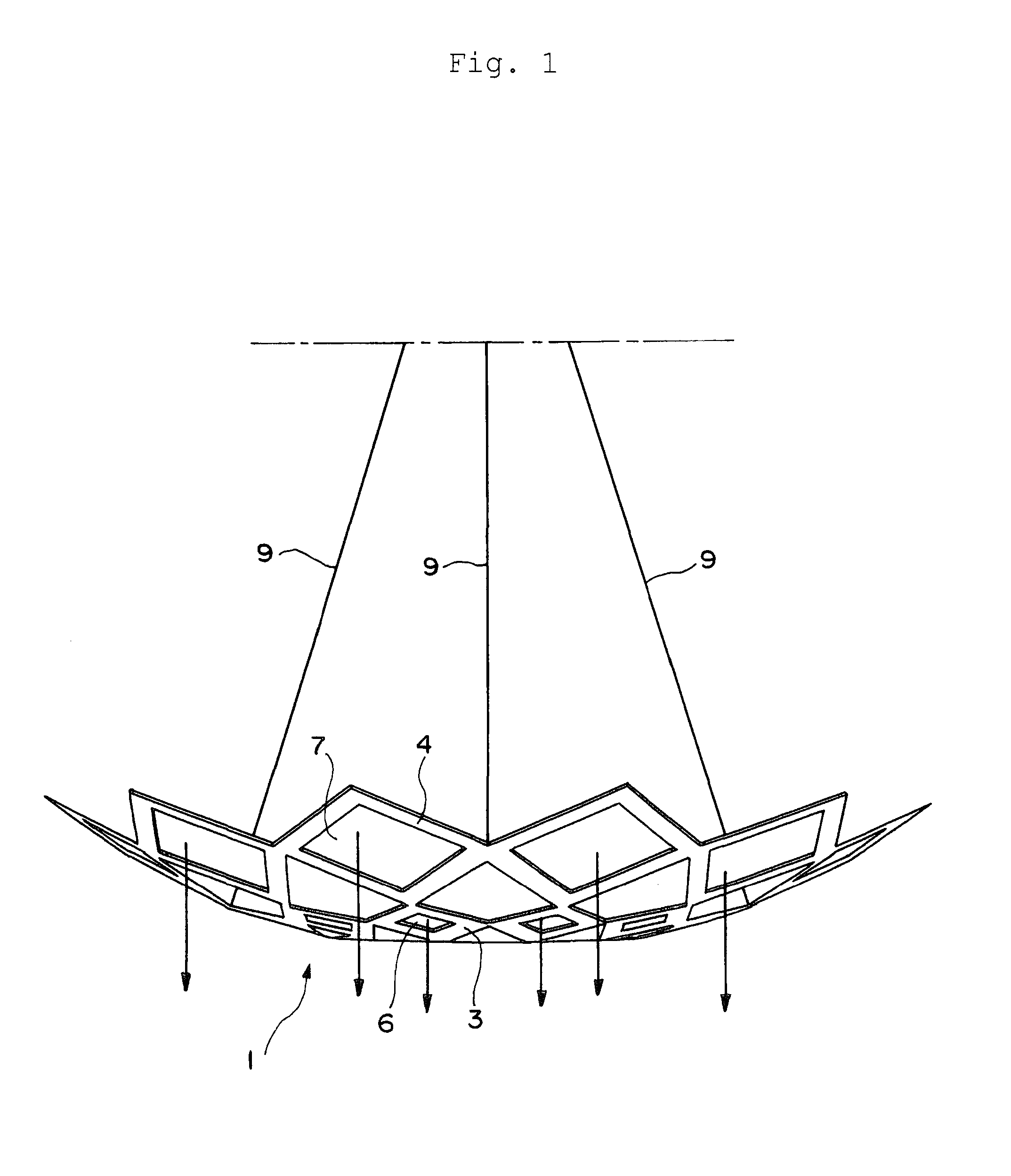
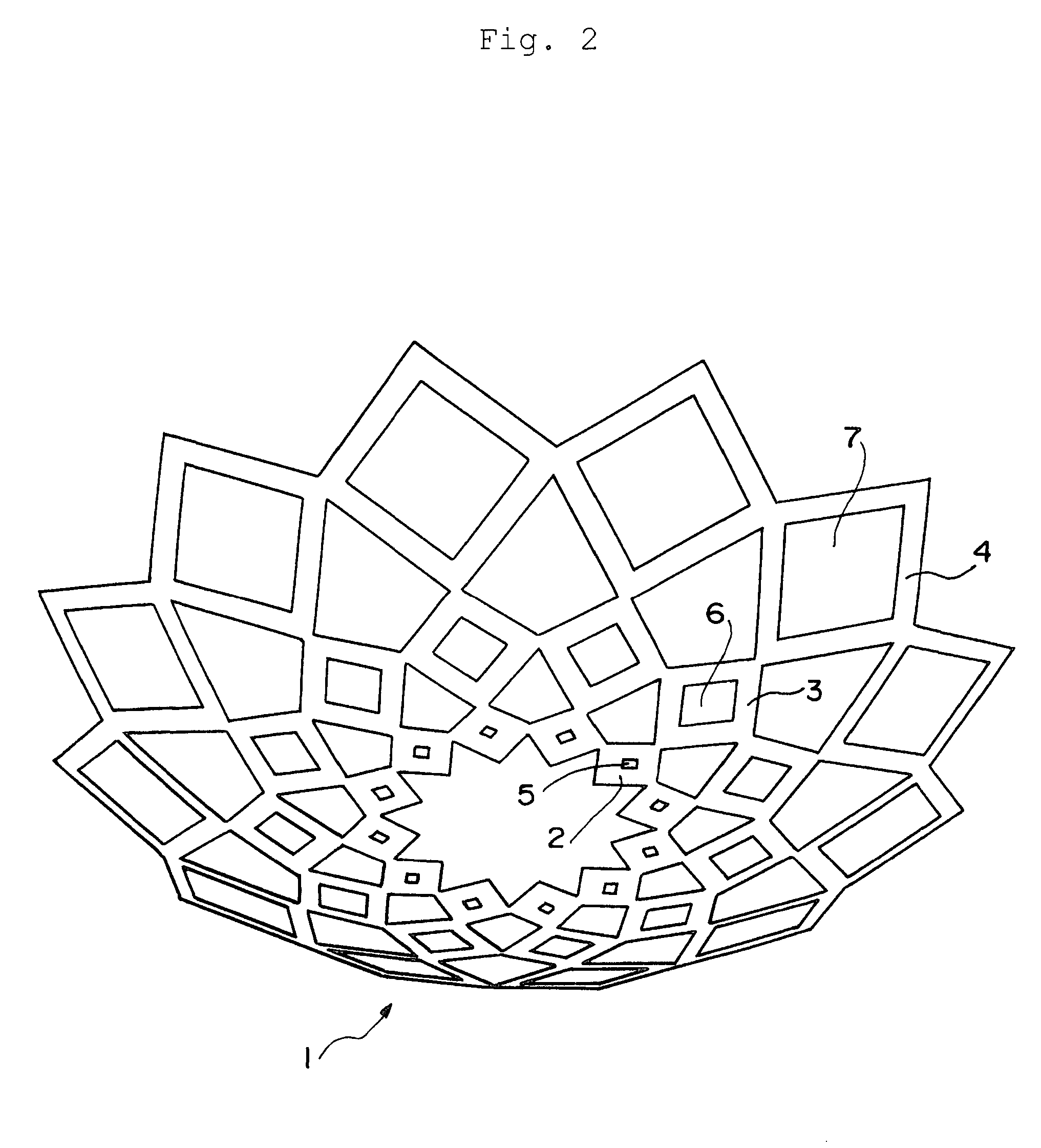
[0023]Hereafter, a lighting apparatus in accordance with the present invention will be described with reference to the preferred embodiment shown in the drawings. FIGS. 1-4 show a general structure in which the present invention is applied to a ceiling-hung lighting apparatus, where FIG. 1 is a front view, FIG. 2 is a perspective view from below of the device with some angle, FIG. 3 is a bottom plan view, and FIG. 4 is a top view showing a schematic structure.

[0024]Hereinafter, a structure of each part in which the same portion is indicated by the same reference numeral will be described with reference to reference numerals. It should be noted that, in order to avoid complications, in each drawing as will be explained, only typical elements are shown by the reference numerals and some of the reference numerals are suitably omitted according to the drawing.

[0025]Reference numeral 1 shows a lighting apparatus in accordance with the present invention. As shown in FIG. 1, this lighting ...


PUM


Abstract

To provide a lighting apparatus in which a high-class feeling and a cubic effect are obtained or an interior design is allowed to have an appearance like a chandelier.
Plane light emitters 5, 6, and 7 constituted by organic EL elements are mounted at planar frames 2, 3, and 4 in the shape of a frame, and the above-mentioned frames 2, 3, and 4 are connected mutually and annularly so that light emitting units of a first-third rings are arranged. Each of the above-mentioned frames which constitute the light emitting units of each ring is formed to be square, and opposed corner portions of the respective frames are connected together. The numbers of frames which constitute the light emitting units of the above-mentioned first-third rings are each set as the same number, and a plane light emitter side in each frame is arranged so as to form a dome shape.

Description

BACKGROUND OF THE INVENTION[0001]1. Field of the Invention[0002]The present invention relates to a lighting apparatus using a plane light source represented by, for example, an organic EL (electroluminescence) element.[0003]2. Description of the Related Art[0004]Since an organic EL element is driven by a low DC voltage, it has a high luminous efficiency and can be reduced in weight and thinned, as well as it has a feature that it generates substantially no heat. Therefore, it is used for a flat panel display (FPD) in some portable devices etc. By employing the element as a plane light source, it is also arranged to be used as, for example, a back light of a liquid crystal display element.[0005]Further, by selection of a material used for an EL luminescence layer, the above-mentioned organic EL element may provide luminescence colors of R (red), G (green), B (blue), or others. Therefore, by using each of the above-mentioned luminescence colors independently or combining a plurality o...

Claims


Application Information

Patent Timeline
Patent Type & Authority Applications(United States)
IPC IPC(8): F21V21/00
CPCF21S8/06F21V15/01F21Y2105/008F21Y2105/00F21V21/005F21Y2115/15F21V17/00H05B33/00
Inventor SONOBE, RYUTA
Owner YAMAGATA PROMOTIONAL ORG FOR INDAL TECH
Why Eureka
Try Eureka