Linear Fluid Timepiece

a fluid timepiece and linear technology, applied in the field of timepieces, can solve the problems of reducing the readability and utility of the parr device, and the inability to read from a maximum of two positions

Inactive Publication Date: 2009-09-03
MEADOWS MICHAEL E
View PDF15 Cites 19 Cited by
  • Summary
  • Abstract
  • Description
  • Claims
  • Application Information

AI Technical Summary

Problems solved by technology

Each of these devices, however, suffers from the deficiency that they can be read from a maximum of two positions (i.e., a position facing the time scale and possibly a second position opposite the first) and can often only be read from one position.
The size of these tubes further reduces th

Method used


Image

  • Linear Fluid Timepiece
  • Linear Fluid Timepiece
  • Linear Fluid Timepiece

Examples


Embodiment Construction

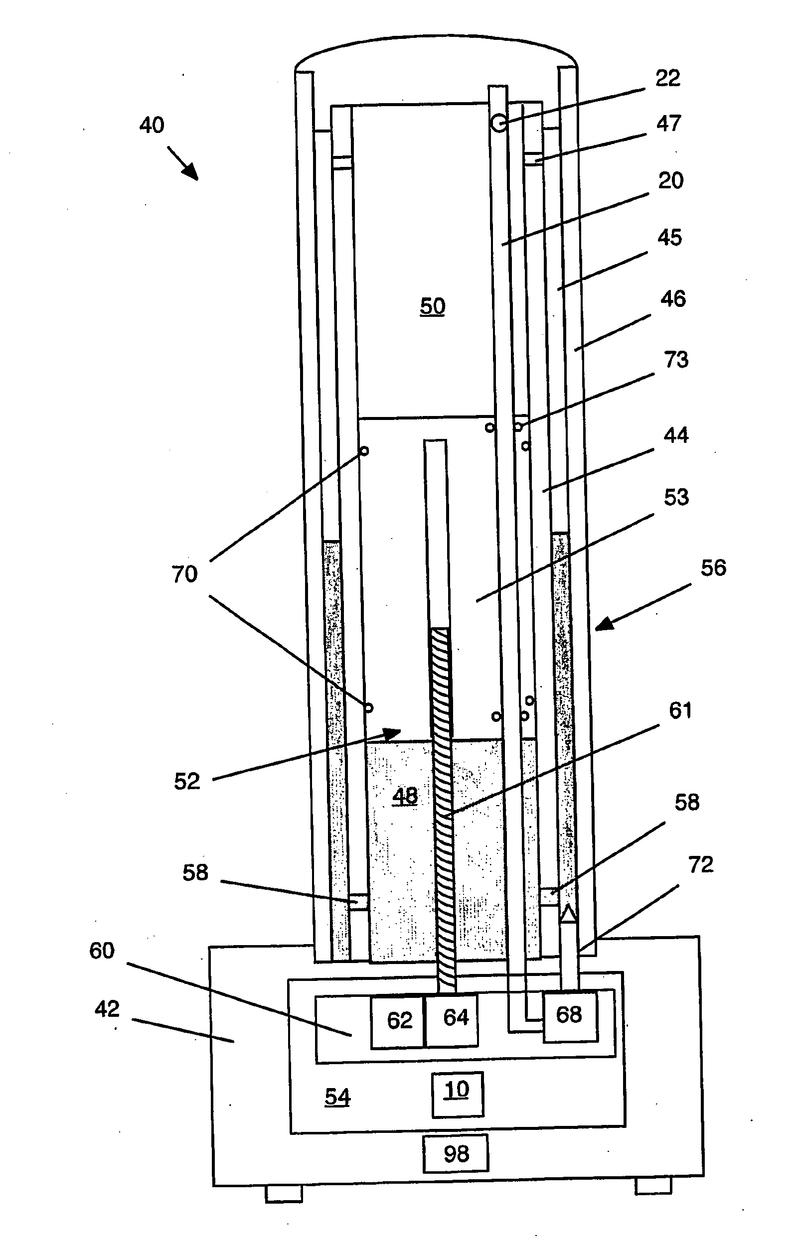
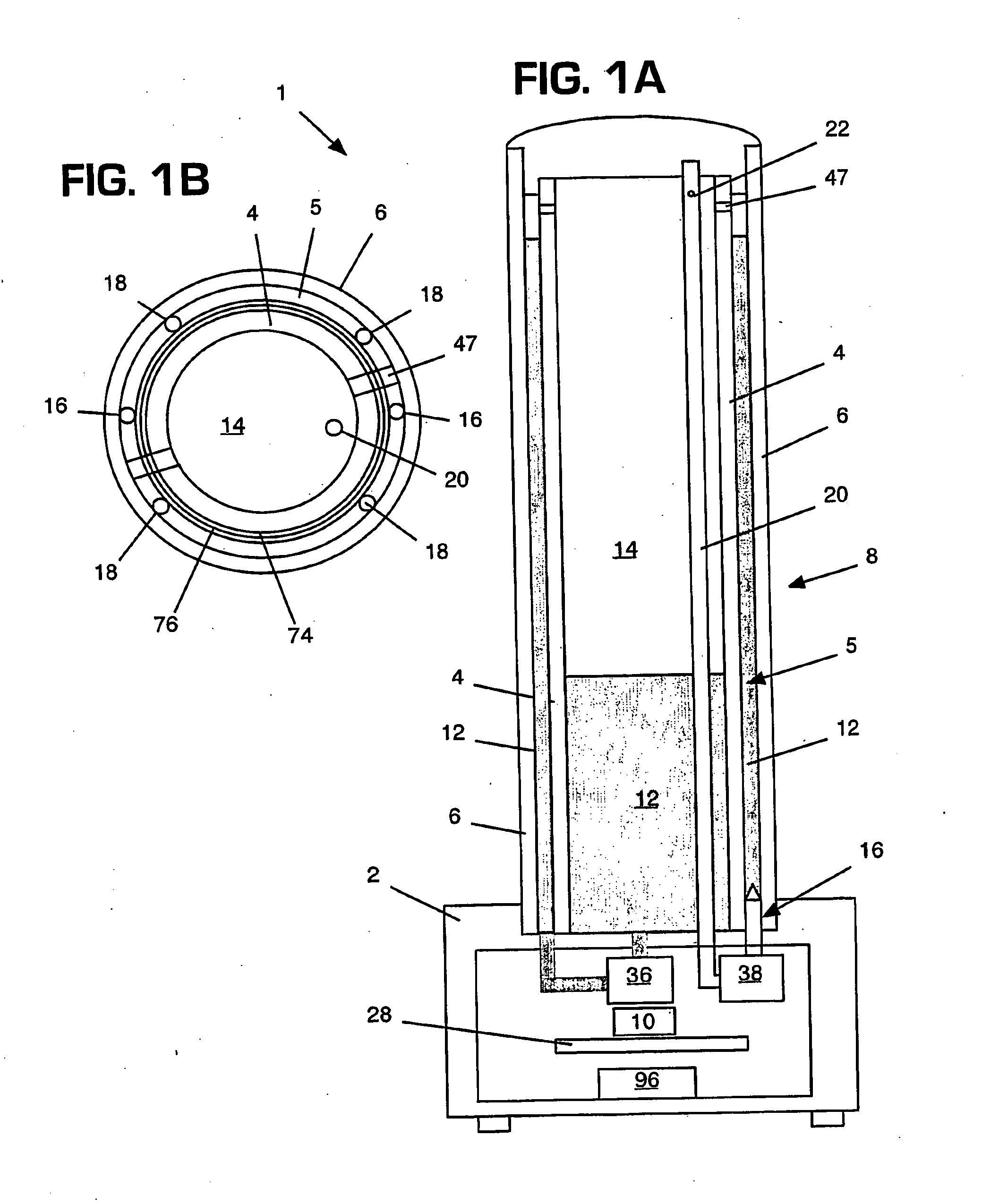
[0019]Referring to FIGS. 1A-1B, side and top cross-sectional views are shown of a timepiece according to the present invention. Generally, the present invention is a vertically-oriented, linear timepiece 1 having two concentric tubes 4, 6. Fluid 12 stored within inner tube 4 is pumped into an annular space 5 between the inner tube 4 and the outer tube 6 to reflect the current time proportional to fluid height. In a preferred embodiment, inner tube 4 is opaque and outer tube 6 is transparent. Outer tube 6 may also be translucent.

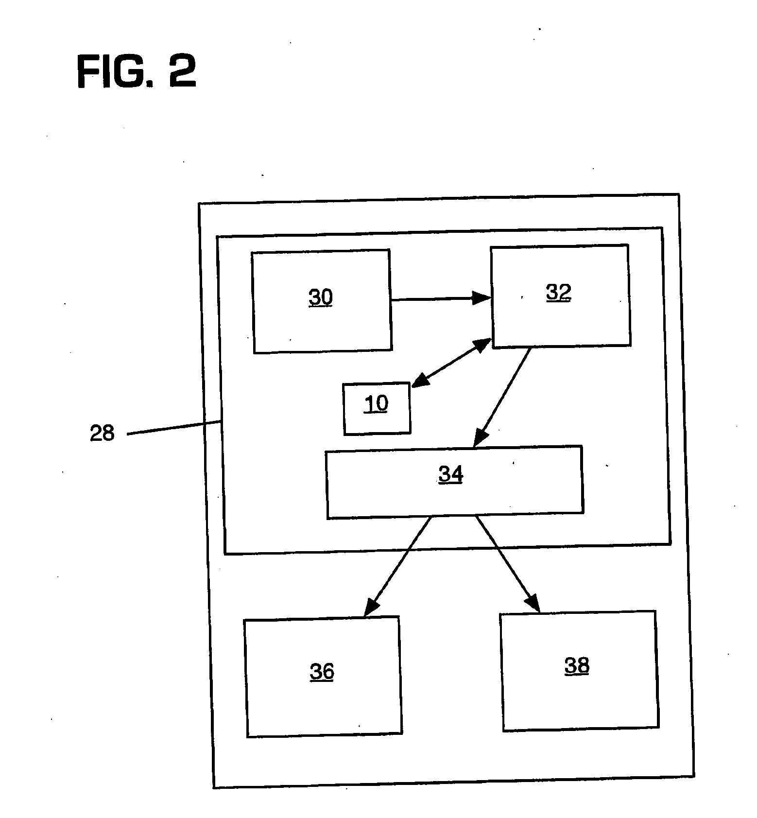
[0020]Time is kept by internal digital circuit 28. Based upon the output from the circuit, fluid level system 36 feeds fluid 12 from within reservoir 14 to reside between inner tube 4 and outer tube 6. Time is read based on the height of the fluid against a reference scale marked on the device. Generally, the level of the fluid will rise with the passage of time, although other embodiments are possible, such as a falling fluid marking the passage of time.

[002...


PUM


Abstract

The present invention provides a timepiece wherein the passage of time is represented by the movement of a fluid column from within an inner tube to a space between the inner tube and a concentric outer tube. In one embodiment, the timepiece includes a display mechanism adapted to adjust a fluid column height based on a capacitance proportional to the fluid column height.

Description

CROSS-REFERENCE TO RELATED APPLICATIONS[0001]This application claims the benefit of co-pending U.S. Provisional Application No. 60 / 636,282, filed 15 Dec. 2004, which is hereby incorporated herein.BACKGROUND OF THE INVENTION[0002](1) Technical Field[0003]The present invention relates generally to timepieces and more particularly to timepieces having a linear scale, wherein the passage of time is represented by the rising or falling of a fluid column.[0004](2) Related Art[0005]Various timepieces having linear scales are known in the art. For example, U.S. Pat. No. 5,331,609 to Gubin and U.S. Pat. No. 3,875,736 to Gulko describe timepieces having linear scales and belt-driven, non-fluid indicators. U.S. Pat. Nos. 3,783,598 to Parr and 4,262,348 to Hess describe timepieces having fluid-filled tubes adjacent a linear scale, wherein movement of fluid within the tubes represents the passage of time. Each of these devices, however, suffers from the deficiency that they can be read from a ma...

Claims


Application Information

Patent Timeline
IPC IPC(8): G04B25/00
CPCG04F13/06G04B19/00
Inventor MEADOWS, MICHAEL E.
Owner MEADOWS MICHAEL E
Why Eureka
Try Eureka