

Endoscope Tip Protector
- Summary
- Abstract
- Description
- Claims
- Application Information
AI Technical Summary
Problems solved by technology
Method used
Image

Examples
Embodiment Construction
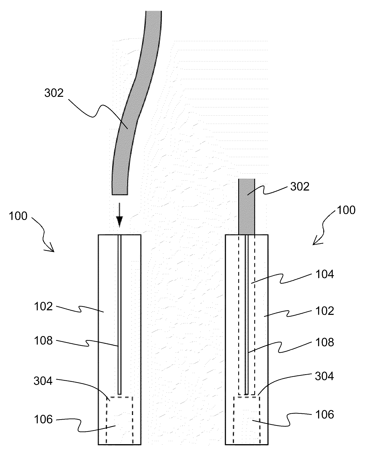
[0015]The invention provides an endoscope tip protector, an endoscope assembly including an endoscope having the ETP affixed thereto, and methods of making and using the ETP and ETP assembly. The ETP may be mounted to or affixed to a distal end of an endoscope to protect the tip. In some embodiments, the ETP may also be configured to facilitate use of the ETP for washing the endoscope between uses. In other embodiments, the ETP may be used to facilitate white light balancing of the endoscope.
[0016]6.1 ETP Designs
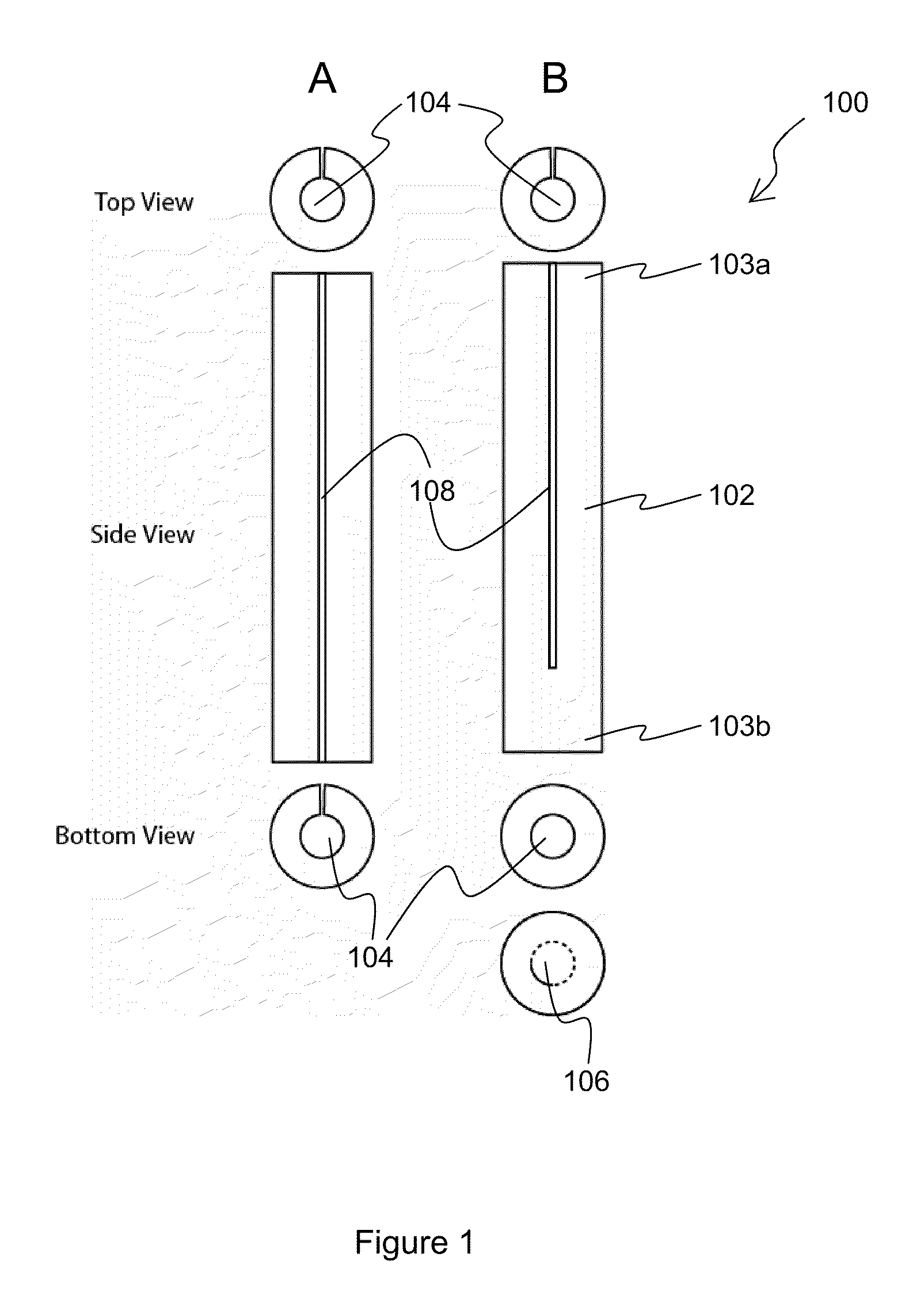
[0017]FIGS. 1-8 illustrate several embodiments of the ETP 100. In the embodiment shown in FIG. 1, ETP 100 may include an ETP body 102, an opening 104 extending at least partially through the ETP body 102, a proximal end 103a, a distal end 103b, a slit 108 extending through the ETP body 102 to the opening 104, and a plug 106 for insertion in a distal end of the opening 104.
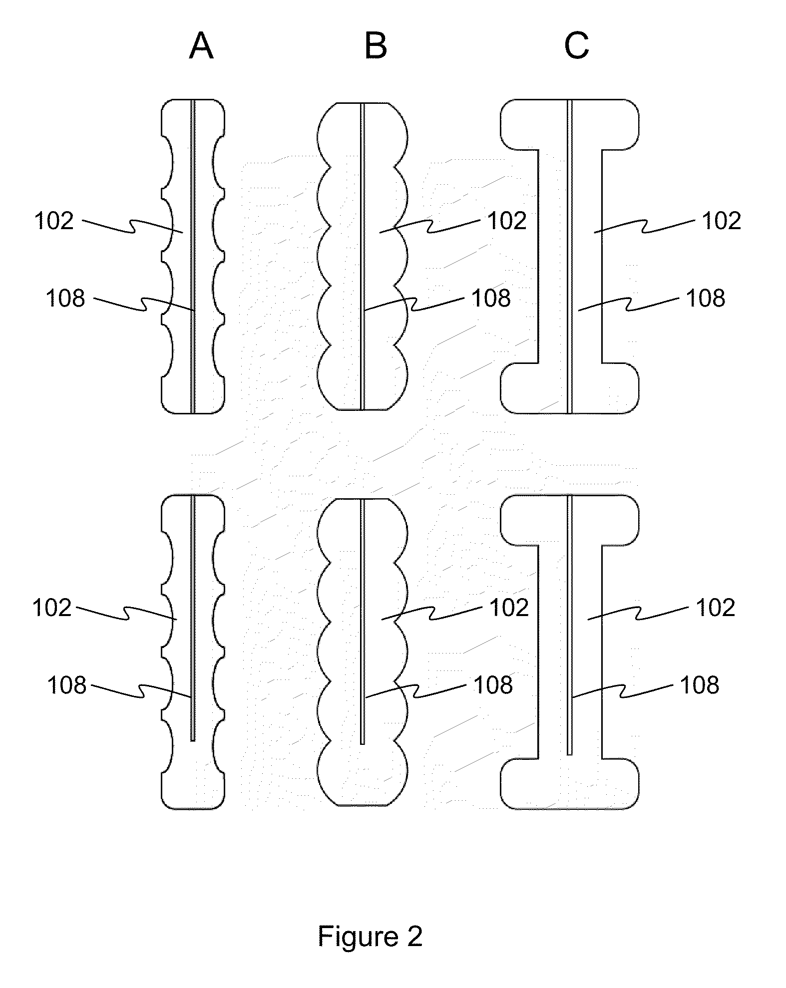
[0018]The ETP body 102 may be provided in any of a wide variety of shapes. Examples include cylindrical,...
PUM
 Abstract
Description
Claims
Application Information