Fluid Drainage Catheter Having an External Flow Path

a catheter and flow path technology, applied in the direction of balloon catheters, catheters, stents, etc., can solve the problems of difficult to completely drain the bladder, difficult to ensure the drainage of fluid, and oftentimes difficult to ensur

Active Publication Date: 2009-09-03
HOLLISTER INCORPORAED
View PDF18 Cites 43 Cited by
  • Summary
  • Abstract
  • Description
  • Claims
  • Application Information

AI Technical Summary

Problems solved by technology

Unfortunately, minimizing residual urine in the bladder depends on substantially accurate positioning of an intermittent catheter which is oftentimes difficult to ensure.
Additionally, however, the soft tissue in the neck area of the bladder sometimes has a tendency to get sucked into the eye, making it difficult to completely drain the bladder.
As a result, intermittent catheters present both a positioning / withdrawing challenge and also an eye blocking problem causing difficulty in ensuring substantially complete bladder drainage.
With regard to Foley catheters, an encrustation problem results from a crystalline buildup which usually begins on the catheter eyes and extends into the lumen of the catheter just below the eyes.
In this connection, it is known that encrustation can lead to complete blocking of the Foley catheter requiring a catheter change well before the recommended time.
As a result, there are problems with both intermittent catheters and Foley catheters which relate to their ability to ensure complete bladder drainage thereby causing them to be less than fully effective in ensuring good urological health.

Method used


Image

  • Fluid Drainage Catheter Having an External Flow Path
  • Fluid Drainage Catheter Having an External Flow Path
  • Fluid Drainage Catheter Having an External Flow Path

Examples


Embodiment Construction

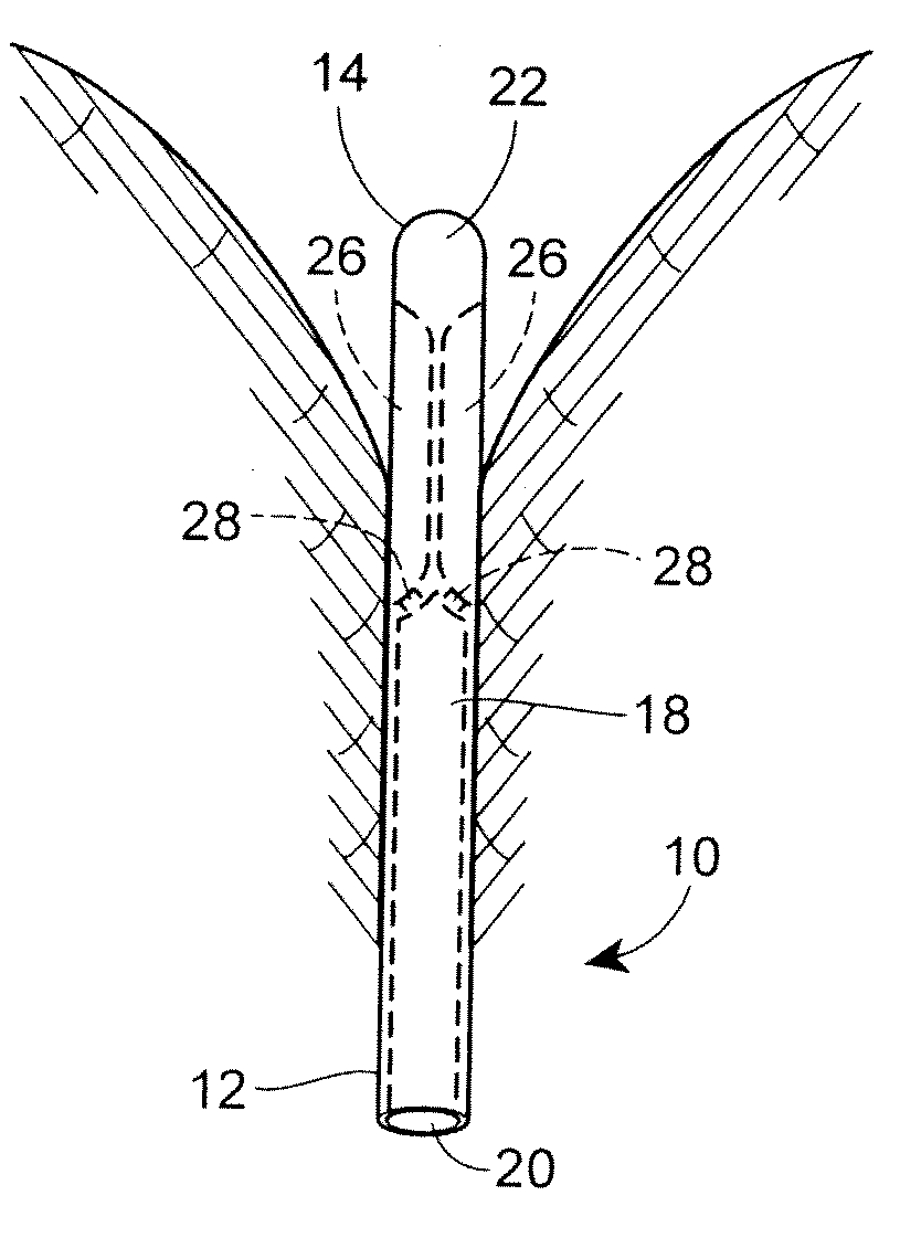
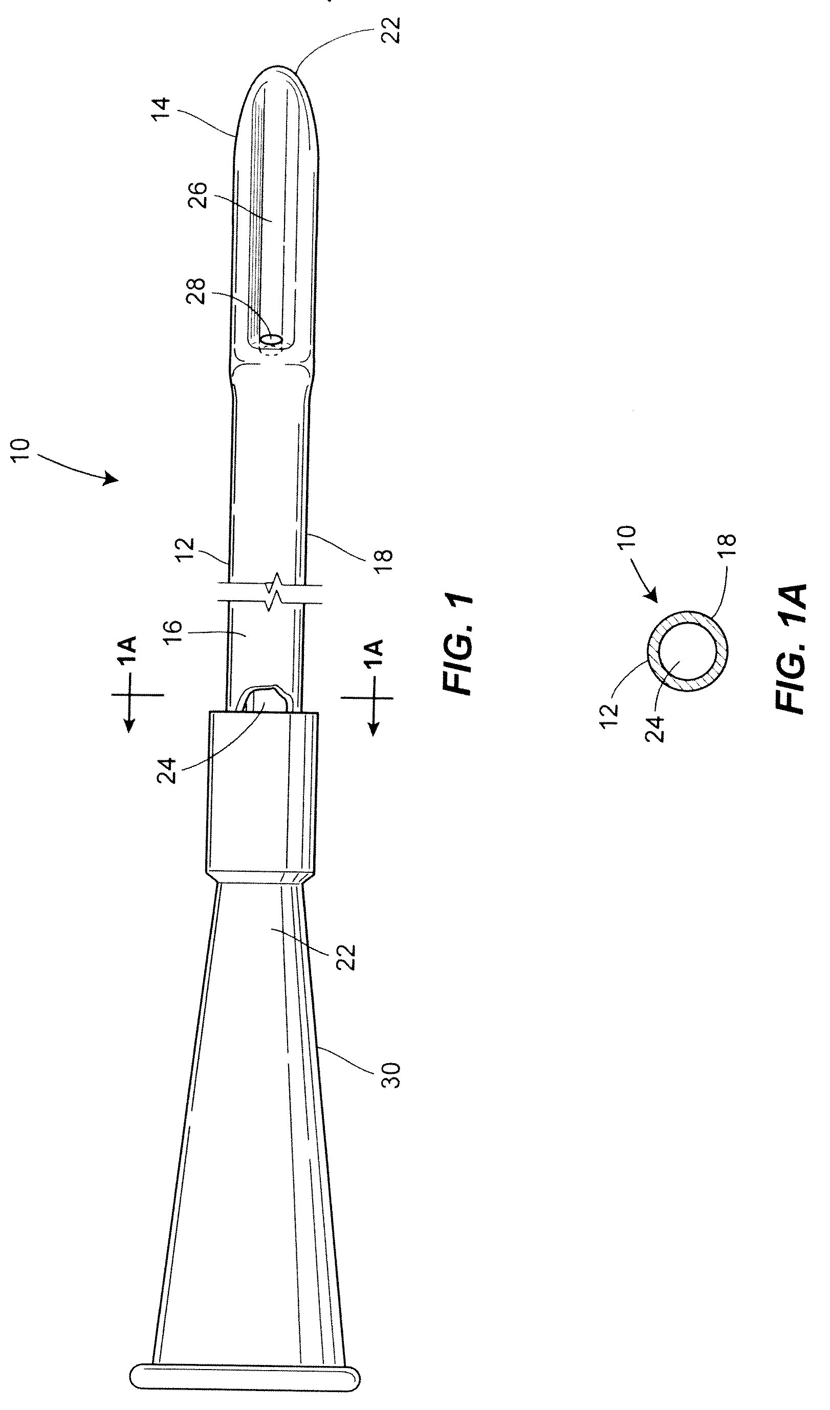
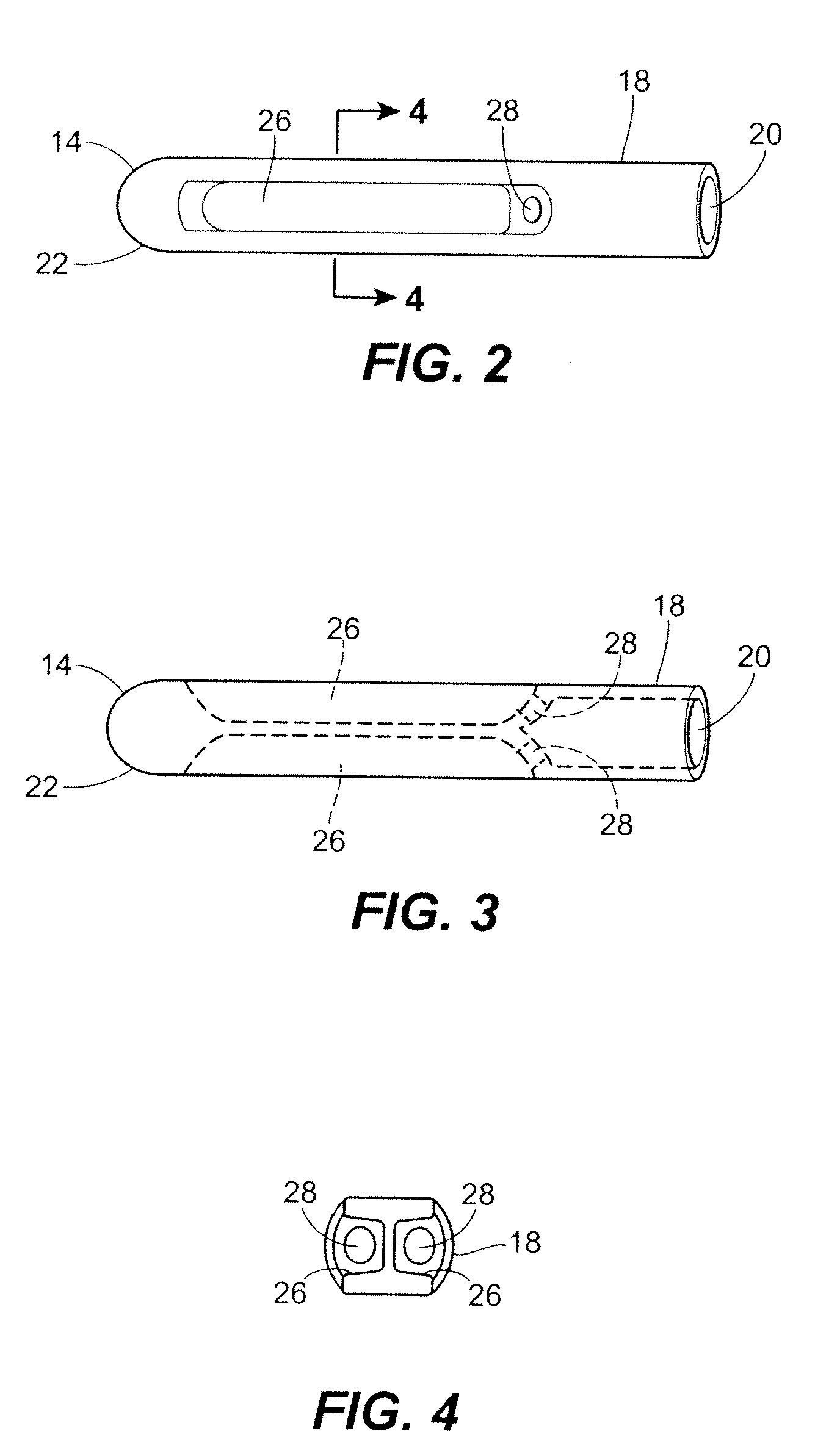
[0033]In the illustrations given, and with reference first to FIG. 1, the reference numeral 10 designates generally a catheter in accordance with the present disclosure. The catheter 10 comprises a catheter tube 12 having a proximal end 14 and a distal end 16 and having a cylindrical wall 18 with a lumen 20 (see FIG. 3) extending generally from the proximal end 14 to the distal end 16 to permit the passage of fluid therethrough. As shown in FIGS. 1 and 1A, the catheter tube 12 is formed such that the proximal end 14 has a closed tip 22 for insertion of the catheter tube into a body cavity and the distal end 16 has an opening as at 24 for the drainage of fluid from the body cavity through the lumen of the catheter tube 12.

[0034]Referring to FIGS. 1-5, the cylindrical wall 18 will be seen to have an outer surface with at least one defined external flow path 26 extending generally in a longitudinal direction from a point in proximity to the closed tip 22 to a point distally thereof. As...


PUM


Abstract

A fluid drainage catheter comprises a catheter tube having a proximal and a distal end and a cylindrical wall with a lumen extending generally from the proximal to the distal end to permit the passage of fluid therethrough. The catheter tube is formed such that the proximal end has a closed tip for insertion of the catheter tube into a body cavity and the distal end has an opening for the drainage of from the body cavity through the lumen of the catheter tube. The cylindrical wall has an outer surface with at least one defined external flow path extending generally in a longitudinal direction from a point in proximity to the closed tip to a point distally thereof. With this arrangement, at least one drainage eye is associated with the defined external flow path and extends completely through the catheter tube from the outer surface to the lumen to permit fluid in the flow path to pass through the drainage eye into the lumen.

Description

FIELD OF THE DISCLOSURE[0001]The present disclosure is generally related to catheters for the drainage of fluid from the body, and in one particular application, to urinary catheters for draining urine from the bladder.BACKGROUND OF THE DISCLOSURE[0002]It is generally well known that catheterization can be an important adjunct to healthcare in many instances. This is known to be the case for draining fluid from a cavity in a body and is particularly the case in connection with urinary catheters which serve to drain urine from the bladder. The regular drainage of the bladder is well recognized as an important function for urological health.[0003]For those suffering from abnormalities of the urinary system, intermittent catheterization has been found to be a good option. Those with such abnormalities often find it desirable to use individually packaged, sterile catheters on a regular basis for drainage of urine from the bladder. Among the more important criteria for intermittent cathe...

Claims


Application Information

Patent Timeline
Patent Type & Authority Applications(United States)
IPC IPC(8): A61M27/00A61F2/958
CPCA61M25/0017A61M25/007A61M2025/1072A61M25/1002A61M25/1011A61M25/04
Inventor HANNON, DAVIDCISKO, JR., GEORGE J.
Owner HOLLISTER INCORPORAED
Why Eureka
Try Eureka