
Intracranial pressure monitor and drainage catheter assembly

a technology of intracranial pressure monitor and catheter assembly, which is applied in the direction of catheters, instruments, applications, etc., can solve the problems of affecting the flow of blood

Active Publication Date: 2011-11-29
EDWARDS LIFESCIENCES CORP
View PDF59 Cites 18 Cited by
  • Summary
  • Abstract
  • Description
  • Claims
  • Application Information

AI Technical Summary

Benefits of technology

[0028]Preferably, the above-described catheter is an integral intracranial pressure monitoring and drainage catheter used in a pressure monitoring assembly that comprises, in basic form, a light source, one or more light transmission means, one or more spectral modulation sensors having optically resonant structures, a photodetector means for converti

Problems solved by technology

Because the brain has a limited capacity to adapt to increases in intracranial volume, once the limit has been met, small increases in volume cause significant increases in intracranial pressure.
However, an increase in the volume of the brain or of cerebral spinal fluid as the result of trauma, and the like, correspondingly constricts the flow of blood and can stop it completely if the increase in fluid is large enough to herniate the brain at the base of the skull.
In such cases, death results.
However, pressure monitoring devices that utilize a column of fluid are easily contaminated with bacteria or air bubbles.
Air bubbles in the line distort the pressure readings and bacterial contamination of the fluid may inadvertently expose the patient to sepsis.
Since the pressures to be monitored are relatively low (0-50 mm Hg), the hydrostatic effects of the fluid column can compromise the readings.
Inherent in all electrical pressure monitoring sensors is a risk of electrical shock that may render them unsuitable for insertion into the interior of the brain.
Introducing electrical currents into the brain risks permanent damage.
However, optical transducers operating upon the principles of intensity modulation suffer from the drawback that any curvature of the fiber optic extraneously reduces the intensity of the reflected light.
One of the disadvantages of the Camino system for monitoring intracranial pressure is that a dedicated stand alone interface module, such as that manufactured by Camino Laboratories, is required to display the pressure and communicate with various commercial patient monitors.
The most reliable intensity modulation catheters, since they require four optical fibers, are larger, more invasive, and therefore inherently more dangerous, than is desirable.
Under conditions of high reflectivity, even a small variation in the frequency of light caused by passage through the Fabry-Perot interferometer dramatically reduces transmission of the frequency-altered light beams.
However, known pressure transducers having this capability, such as those useful for monitoring intracranial pressure arg expensive and cumbersome.
If a second hole is drilled to insert a drain, the risk of trauma is obviously doubled.
However, the assembly is subject to breakage, requires a large drillhole to accommodate the bolt, and is assembled out of standard connectors that are subject to leakage and, therefore, provide sources of infection.
However, an optical pressure monitoring and drainage assembly is highly desirable because the accuracy of fluid column intracranial sensors is destroyed by simultaneous drainage of cerebrospinal fluids.
However, an implanted catheter, such as an intracranial catheter, cannot be removed for calibration and replaced without introducing the risk of infection.

Method used


Image

  • Intracranial pressure monitor and drainage catheter assembly
  • Intracranial pressure monitor and drainage catheter assembly
  • Intracranial pressure monitor and drainage catheter assembly

Examples


Embodiment Construction

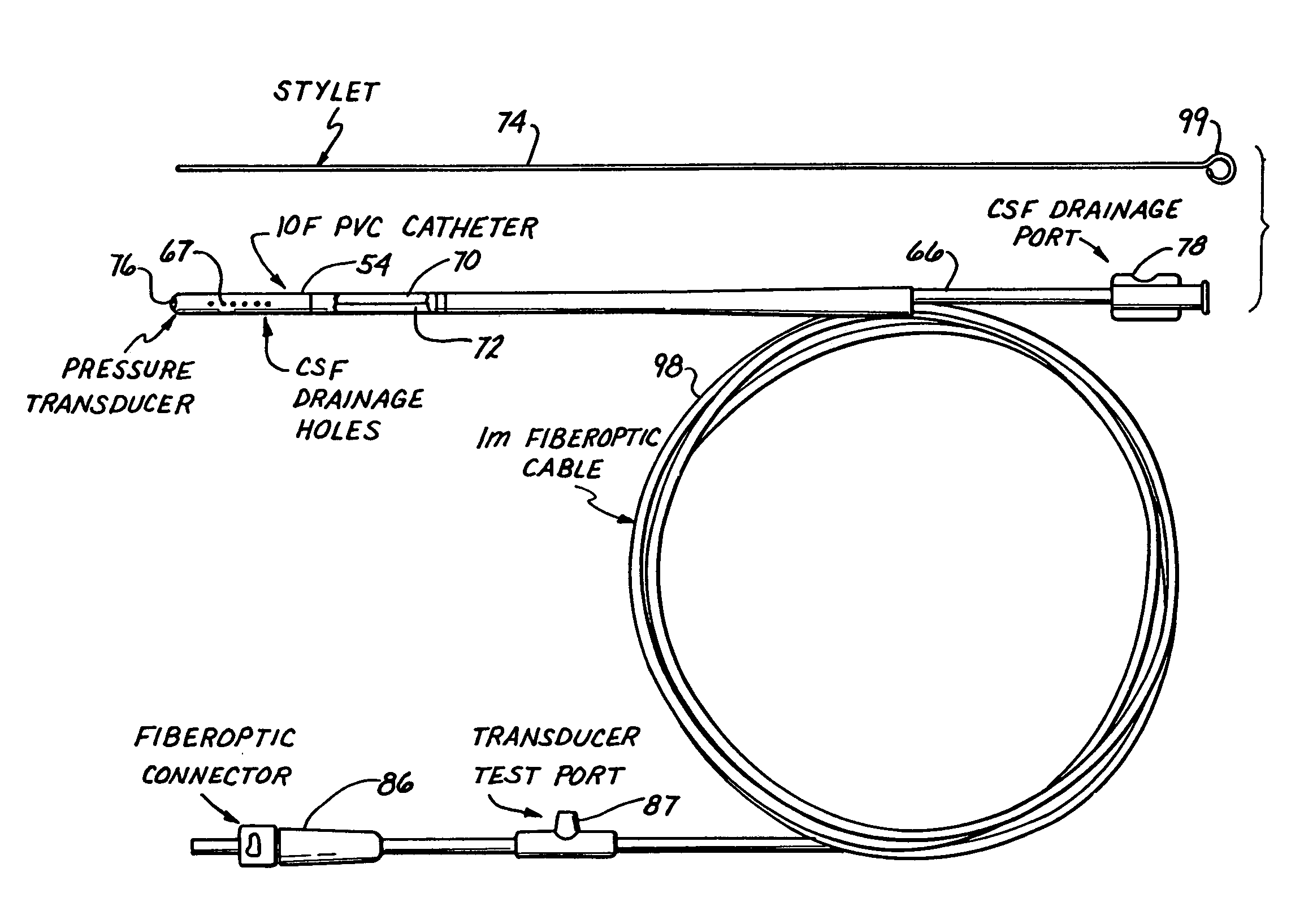
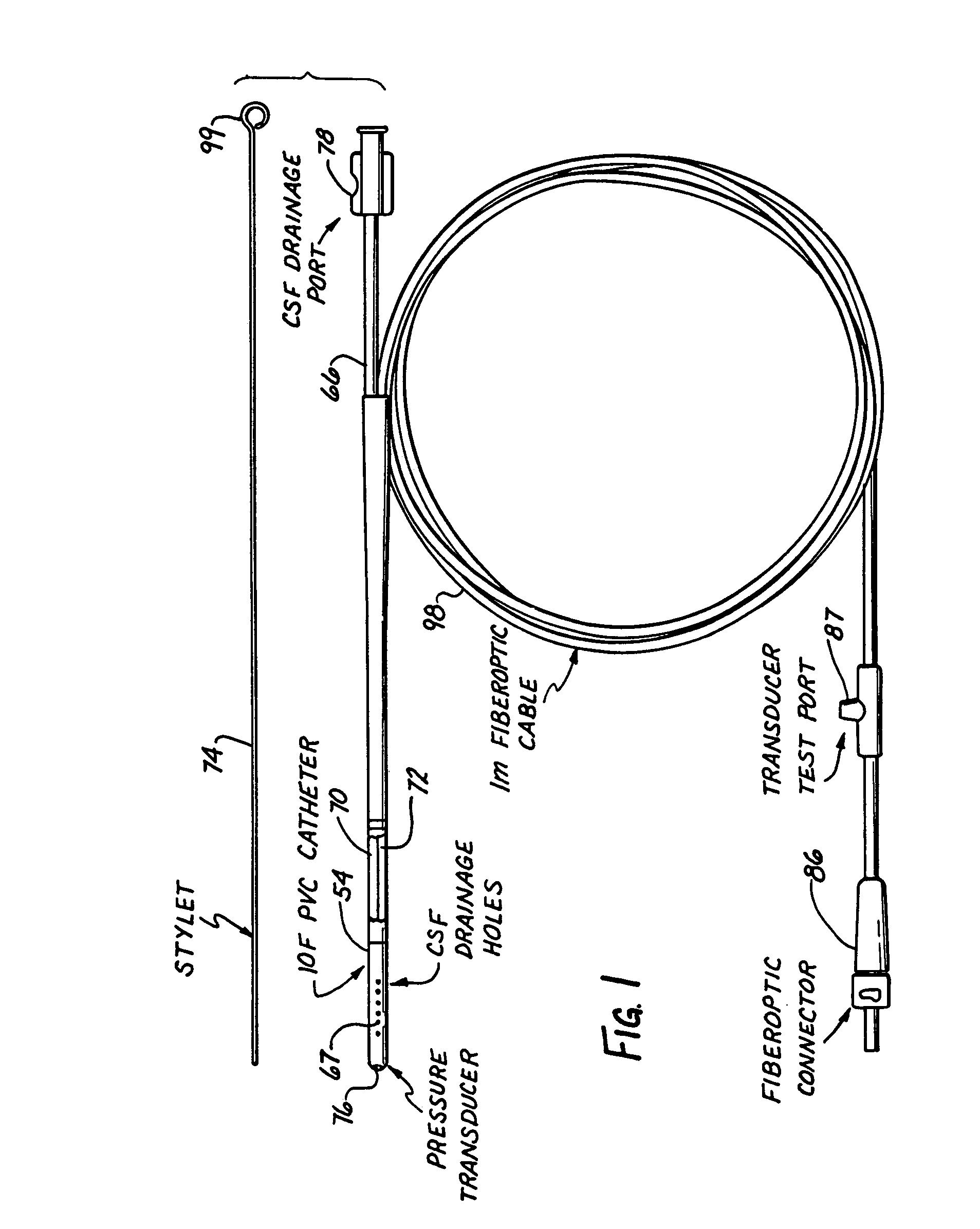
[0049]In the preferred embodiment, the catheter is a dual lumen catheter adapted for insertion into the ventricular and / or parenchymal spaces of the brain of humans and other mammals for measuring intracranial pressure and for simultaneously draining cerebrospinal fluids. As shown in FIG. 1, the catheter comprises catheter housing 54, which encloses first lumen 70 and optional second lumen 72.

[0050]Catheter housing 54 is an elongate flexible tube closed at the distal end, except for sensor aperture 76, to facilitate insertion of the catheter into the environment whose pressure is to be monitored. Sensor aperture 76 opens into the distal end of first lumen 70 and provides external fluid access to the pressure sensor.

[0051]Usually catheter housing 54 is extruded from a biocompatible plastic material, preferably silicone rubber. Catheter housing 54 is elongate, flexible and sized to be passed through a borehole in the skull and received within the brain.

[0052]First lumen 70 extends con...


PUM


Abstract

A monitor-driven intracranial catheter assembly including dual lumen catheter for monitoring intracranial pressure via a pressure sensor located in one lumen while simultaneously draining cerebrospinal fluid through another lumen. A third lumen can also be provided with a side port for receiving a stylet. The stylet is used as a stiffening agent to aid in advancing the catheter into the patient's brain. The pressure sensor is preferably a spectral modulation sensor that communicates with a photodetector apparatus by means of a single optical fiber, thus minimizing the diameter of the catheter. The photodetector is self-correcting for signal errors caused by temperature change, changes in intensity of the input light, and transmission losses within the optical apparatus. Moreover, the photodetector operates off the output voltage of the standard hospital monitor by “scaling” the signal from the monitor to provide a pressure measurement signal that emulates the output of a piezoresistive strain gauge sensor or Wheatstone bridge. Therefore, the entire catheter assembly is designed to be used with any of the common types of hospital monitors. The pressure monitoring catheter assembly can be used in any situation requiring very sensitive pressure measurements and can be zeroed and calibrated in situ.

Description

[0001]This is a continuation-in-part of U.S. patent application Ser. No. 419,938 filed Oct. 11, 1989 now abandoned.BACKGROUND OF THE INVENTION[0002]1. Field of the Invention[0003]The present invention relates to an intracranial catheter that is insertable by a scalp tunnel insertion technique and a related catheter assembly for monitoring fluid pressure while simultaneously removing a part of the fluid or infusing thereinto a second fluid. More particularly, the invention relates to a monitor-driven intracranial catheter assembly including a dual lumen catheter having an in situ pressure monitoring device at the distal tip for continuously monitoring intracranial pressure via one lumen while optionally conducting simultaneous drainage or sampling of cerebrospinal fluid through the other lumen.[0004]2. Description of the Prior Art[0005]The skull is a bony housing of fixed volume containing three types of matter—blood, brain and cerebrospinal fluid—each of which occupies a portion of ...

Claims


Application Information

Patent Timeline
IPC IPC(8): A61M25/00A61M5/178A61M39/00A61M39/10A61M25/16A61M25/18A61B5/00A61B5/03A61M1/00A61M27/00G01L9/00
CPCA61B5/031A61B5/412G01L9/0079G01L9/0077A61M27/006A61B2562/0261
Inventor HALL, JOHN P.BECKMAN, RONALD B.
Owner EDWARDS LIFESCIENCES CORP
Learn More