
Rack and pinion steering gear with self-adjusting rack bearing

a rack bearing and steering gear technology, which is applied in the direction of gears, manufacturing tools, transportation and packaging, etc., can solve the problems of enlarge the mesh clearance between the pinion shaft and the rack, the assembly, including the rack bearing, is also subject to wear over the full life of the steering gear, and the rack and pinion gears are subject to a rapid period of wear

Active Publication Date: 2009-09-10
STEERING SOLUTIONS IP HLDG +1
View PDF21 Cites 46 Cited by
  • Summary
  • Abstract
  • Description
  • Claims
  • Application Information

AI Technical Summary

Benefits of technology

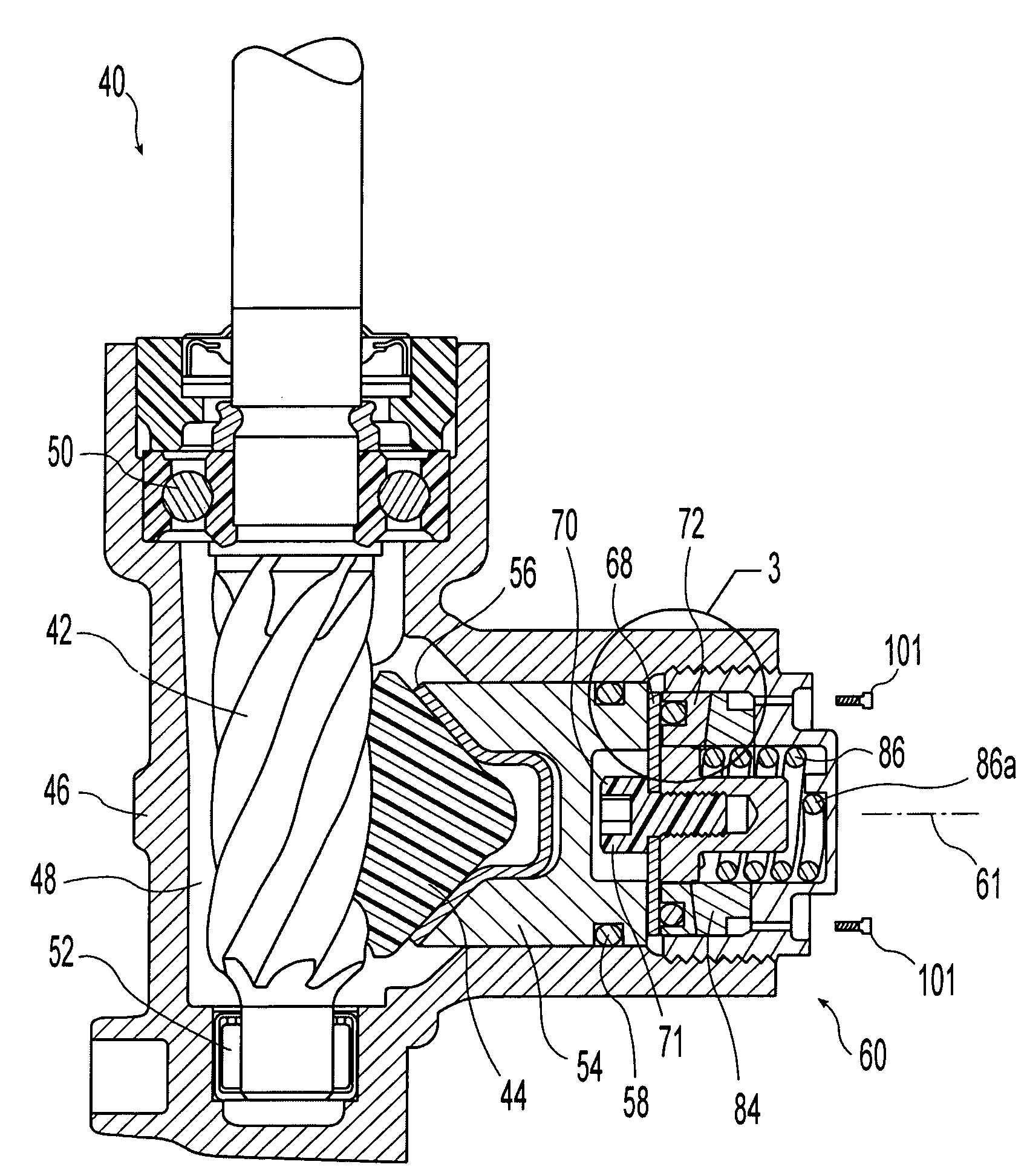
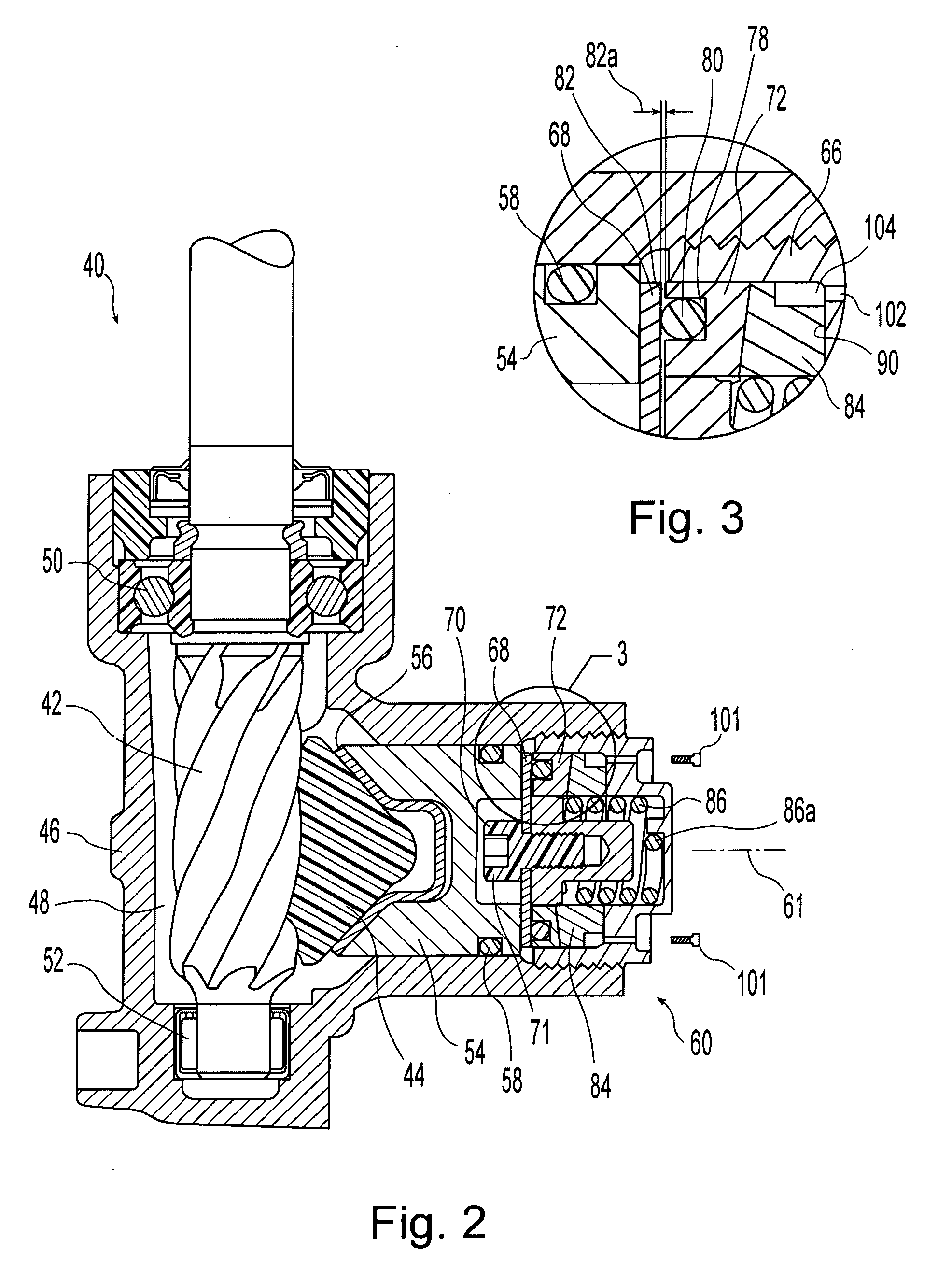
[0011]The invention comprises, in one form thereof, a rack and pinion steering gear assembly that includes a housing forming a housing interior, a pinion shaft, and a rack operably engaged with the pinion shaft wherein the shaft and the rack are at least partially disposed within the housing interior. A rack bearing is engaged with the rack and disposed opposite the pinion shaft. A biasing assembly is operably coupled with the rack bearing and biases the rack bearing into engagement with the rack along a biasing axis whereby the rack bearing urges the rack into engagement with the pinion shaft. The biasing assembly includes a gross adjustment member, a bearing assembly and an accumulative adjustment assembly. The gross adjustment member is securable to the housing at a plurality of axial positions relative to the biasing axis and is fixed to the housing at a selected one of the positions during initial assembly of the steering gear assembly. The bearing assembly includes a bearing member, a first adjustment member and a first biasing member. The bearing member is bearingly coupled with the rack bearing and the first adjustment member is relatively moveably coupled with the bearing member wherein relative movement along the biasing axis between the first adjustment member and the bearing member defines a compliance zone. The compliance zone allows the bearing member to move in response to dimensional variations in the pinion shaft and the rack during operation of the steering gear assembly. The first biasing member biases the bearing member along the biasing axis away from the first adjustment member and toward the rack bearing. The accumulative adjustment assembly is operably disposed between the gross adjustment member and the first adjustment member and is disposed entirely within the housing interior. The accumulative adjustment assembly has a second biasing member that is operably coupled with the first adjustment member and urges the first adjustment member toward the rack bearing along the biasing axis. The second biasing member exerts an effective axial force that is insufficient to compress the compliance zone. The first adjustment member is operably coupled with the biasing assembly such that the first adjustment member is relatively moveable toward the rack bearing in continuously-variable axial movements and axial movement of the first adjustment member away from the rack bearing is prevented.
[0012]The invention comprises, in another form thereof, a rack and pinion steering gear assembly that includes a housing forming a housing interior, a pinion shaft, and a rack operably engaged with the pinion shaft wherein the shaft and the rack are at least partially disposed within the housing interior. A rack bearing is engaged with the rack and disposed opposite the pinion shaft. A biasing assembly is operably coupled with the rack bearing and biases the rack bearing into engagement with the rack along a biasing axis whereby the rack bearing urges the rack into engagement with the pinion shaft. The biasing assembly includes a gross adjustment member, a bearing assembly and an accumulative adjustment assembly. The gross adjustment member is securable to the housing at a plurality of axial positions relative to the biasing axis and is fixed to the housing at a selected one of the positions during initial assembly of the steering gear assembly. The bearing assembly includes a bearing member, a first adjustment member and a first biasing member. The bearing member is bearingly coupled with the rack bearing and the first adjustment member is relatively moveably coupled with the bearing member such that relative movement along the biasing axis between the first adjustment member and the bearing member defines a compliance zone. The compliance zone allows the bearing member to move in response to dimensional variations in the pinion shaft and the rack during operation of the steering gear assembly. The first biasing member biases the bearing member along the biasing axis away from the first adjustment member and toward the rack bearing. The accumulative adjustment assembly is operably disposed between the gross adjustment member and the first adjustment member and is disposed entirely within the housing interior. The accumulative adjustment assembly has a second biasing member and a second adjustment member. The second biasing member urges the second adjustment member to rotate about the biasing axis in a first rotational direction relative to the gross adjustment member. Rotation of the second adjustment member in the first rotational direction urges the first adjustment member toward the rack bearing along the biasing axis. The second biasing member exerts an ef...

Problems solved by technology

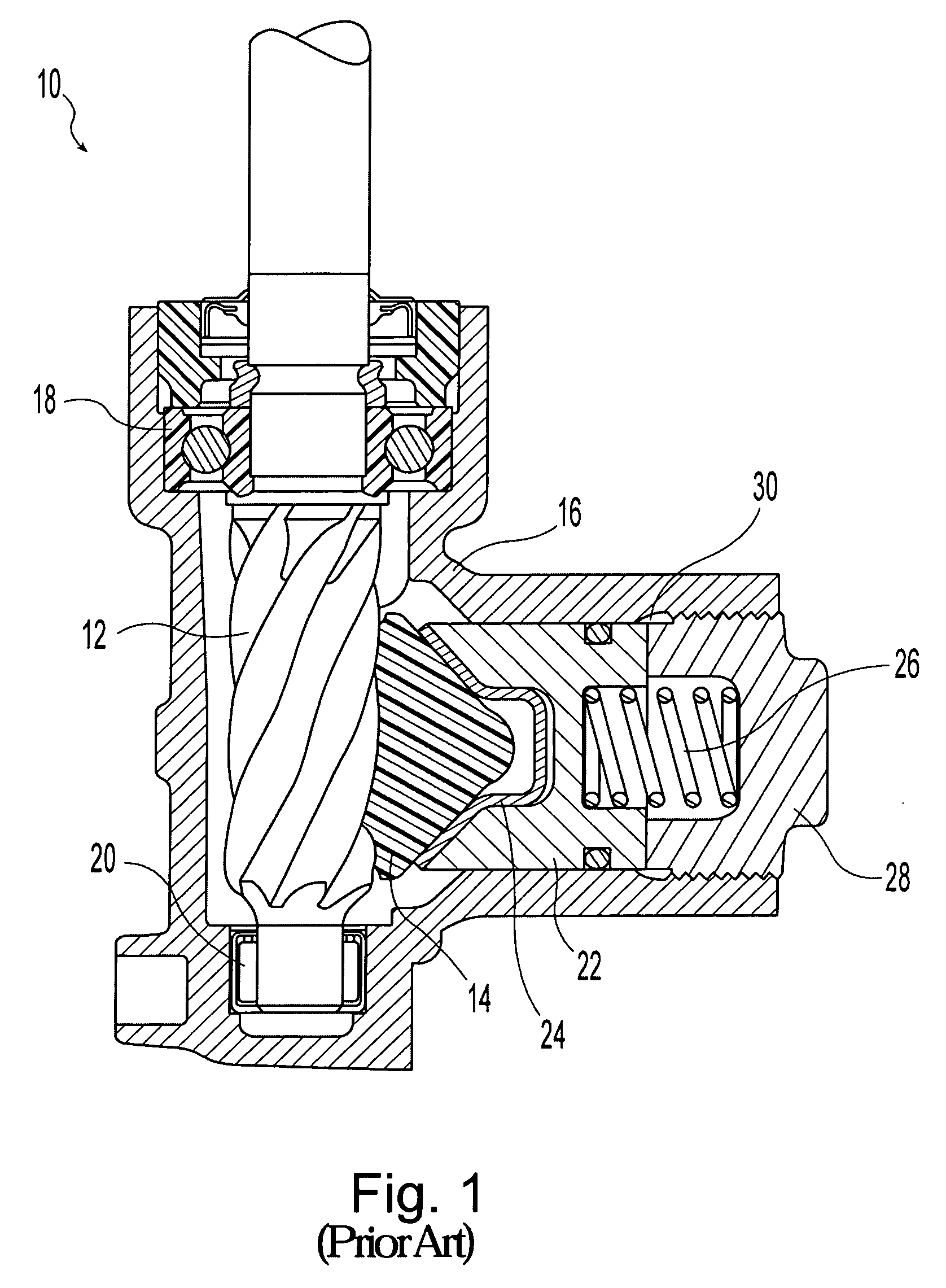
During the initial period of use of the rack and pinion steering gear, typically referred to as the “break-in” period, the rack and pinion gears are subject to a rapid period of wear which can enlarge the mesh clearance between the pinion shaft and rack.
The assembly, including the rack bearing, is also subject to wear over the full life of the steering gear.
If the mesh clearance between the pinion shaft and rack becomes too large, it can lead to rattle noise and ultimately customer dissatisfaction and complaints.
During initial assembly, if plug 28 is installed at too great a distance from rack 14, the working range of spring 26 will be undesirably large and rattle may result.

Method used


Image

  • Rack and pinion steering gear with self-adjusting rack bearing
  • Rack and pinion steering gear with self-adjusting rack bearing
  • Rack and pinion steering gear with self-adjusting rack bearing

Examples


embodiment 140

[0041]Alternative embodiment 140 of a rack and pinion steering gear assembly in accordance with the present invention is illustrated in FIGS. 5 and 6. The pinion shaft 42, rack 44, housing 46 and rack bearing 54 are similar to those employed in steering gear 40, however, biasing assembly 160 does differ from biasing assembly 60 in several aspects which are described in greater detail below. Biasing assembly 160 includes a bearing assembly 162 engaged with rack bearing 54 and exerting a bearing force thereon, an accumulative adjustment assembly 164 to account for the wear of pinion shaft 42 and rack 44 and a gross adjustment member 166.

[0042]As illustrated in FIG. 5, bearing assembly 162 includes a bearing member 168 that is engaged with rack bearing 54, an adjustment member 184 and a biasing member 180 located between bearing member 168 and adjustment member 184. Bearing member 168 and adjustment member 184 each include an annular groove in which biasing member 180 is disposed. In t...


PUM

PropertyMeasurementUnit
Angleaaaaaaaaaa
Forceaaaaaaaaaa
Torqueaaaaaaaaaa

Abstract

A steering gear assembly with a pinion shaft, rack, housing and rack bearing. A biasing assembly biases the rack bearing against the rack and into engagement with the pinion. The biasing assembly includes a gross adjustment member secured to the housing, a bearing assembly with a bearing member coupled with the rack bearing and a first adjustment member. A first biasing member is coupled with the bearing member and first adjustment member which are relatively moveable to thereby define a compliance zone to allow for dimensional variations in the meshing of the rack and pinion. An adjustment biasing assembly is operably disposed between the gross adjustment member and the bearing assembly. The adjustment biasing assembly is disposed entirely within the housing, includes a second biasing member, and urges the first adjustment member toward the rack bearing in continuously-variable axial movements while preventing movement away from the rack bearing.

Description

BACKGROUND OF THE INVENTION[0001]1. Field of the Invention[0002]The present invention relates to rack and pinion steering gear assemblies and rack bearings used therewith.[0003]2. Description of the Related Art[0004]Rack and pinion steering gear assemblies include an intermeshed pinion shaft and rack. A rack bearing is typically positioned to bear against the rack and bias it toward the pinion shaft to maintain the mesh clearance between the pinion shaft and rack. When a rack and pinion steering gear is assembled, the rack bearing is adjusted to provide a desired mesh clearance between the pinion gear and rack. During the initial period of use of the rack and pinion steering gear, typically referred to as the “break-in” period, the rack and pinion gears are subject to a rapid period of wear which can enlarge the mesh clearance between the pinion shaft and rack. The assembly, including the rack bearing, is also subject to wear over the full life of the steering gear. If the mesh clea...

Claims


Application Information

Patent Timeline
IPC IPC(8): F16H1/04B23P19/04
CPCB62D3/123Y10T29/53796Y10T74/1967F16H55/283
Inventor EICKHOLT, MICHAEL A.
Owner STEERING SOLUTIONS IP HLDG
Learn More