Leveling Mechanism For Floor Drain

a technology of floor drains and leveling mechanisms, which is applied in the direction of pipes, building components, constructions, etc., can solve the problems of problems that can occur and develop during the installation of these types of drains

Active Publication Date: 2009-09-10
ZURN INDS
View PDF26 Cites 18 Cited by
  • Summary
  • Abstract
  • Description
  • Claims
  • Application Information

AI Technical Summary

Benefits of technology

[0011]In a further embodiment, a method for leveling a floor drain relative to a floor surface is provided. The method includes the step of providing a floor drain having a head with a top surface, a leveling member, and a frame having a top surface and a bottom surface. The bottom surface of the frame is positioned adjacent the top surface of the head and the leveling member is positioned between the head and the frame. The method further includes the step of displacing the leveling member in a first direction such that the leveling member engages the bottom surface of the frame. The engagement of the leveling member with the bottom surface of the frame may displace the bottom surface of the frame to substantially level the frame with the floor surface.

Problems solved by technology

Referring to FIG. 2, a problem develops during the installation of these types of drains due to variances associated with the finished floor height and pitch.
A problem can occur at this time if the head unit 20 of the drain assembly was incorrectly adjusted to compensate for the total thickness of the finished floor surface 55, e.g., the tile and thin set mortar.

Method used


Image

  • Leveling Mechanism For Floor Drain
  • Leveling Mechanism For Floor Drain
  • Leveling Mechanism For Floor Drain

Examples


Embodiment Construction

[0025]For purposes of the description hereinafter, spatial orientation terms, if used, shall relate to the referenced embodiment as it is oriented in the accompanying drawing figures or otherwise described in the following detailed description. However, it is to be understood that the embodiments described hereinafter may assume many alternative variations and embodiments. It is also to be understood that the specific devices illustrated in the accompanying drawing figures and described herein are simply exemplary and should not be considered as limiting.

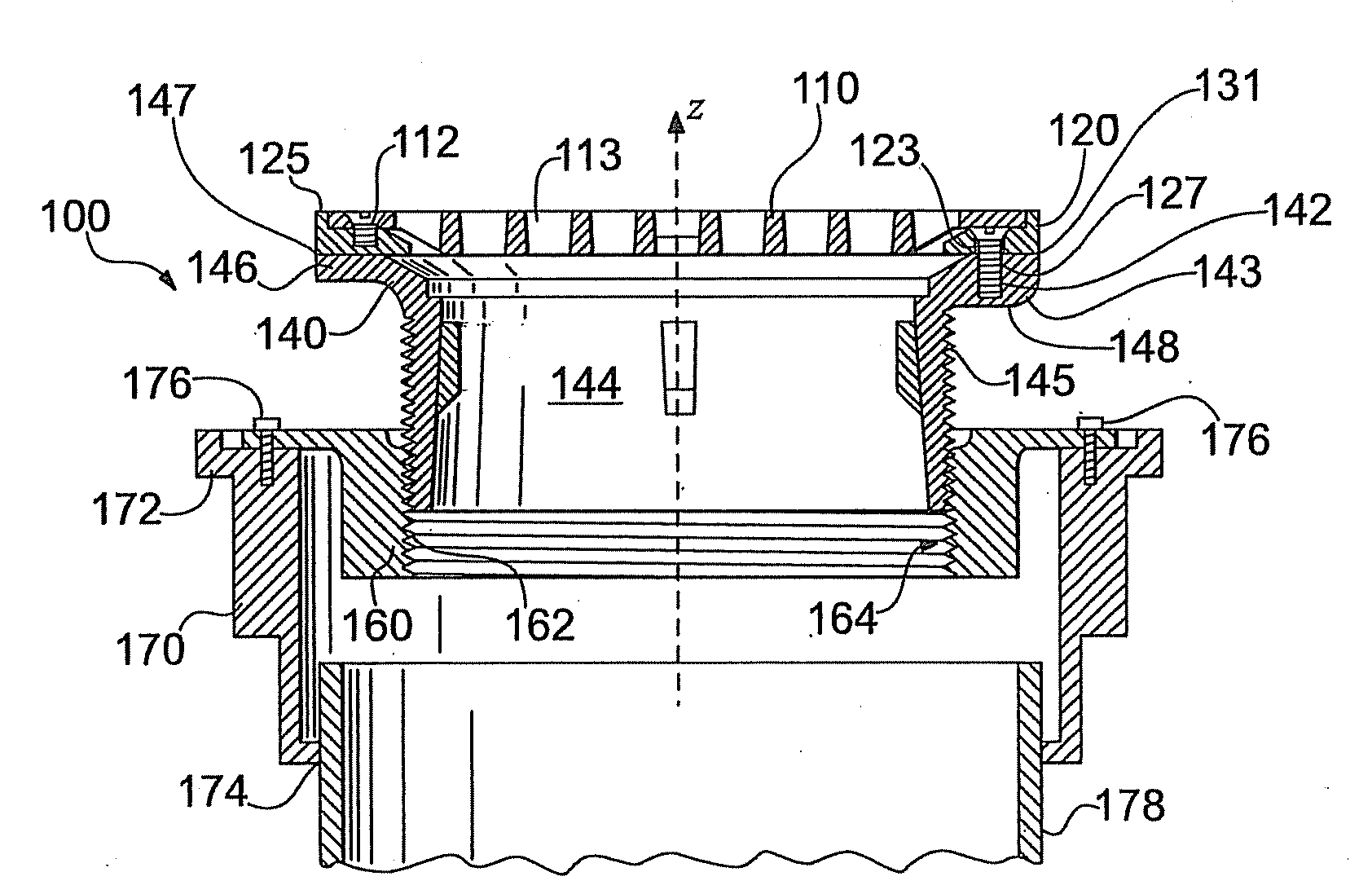
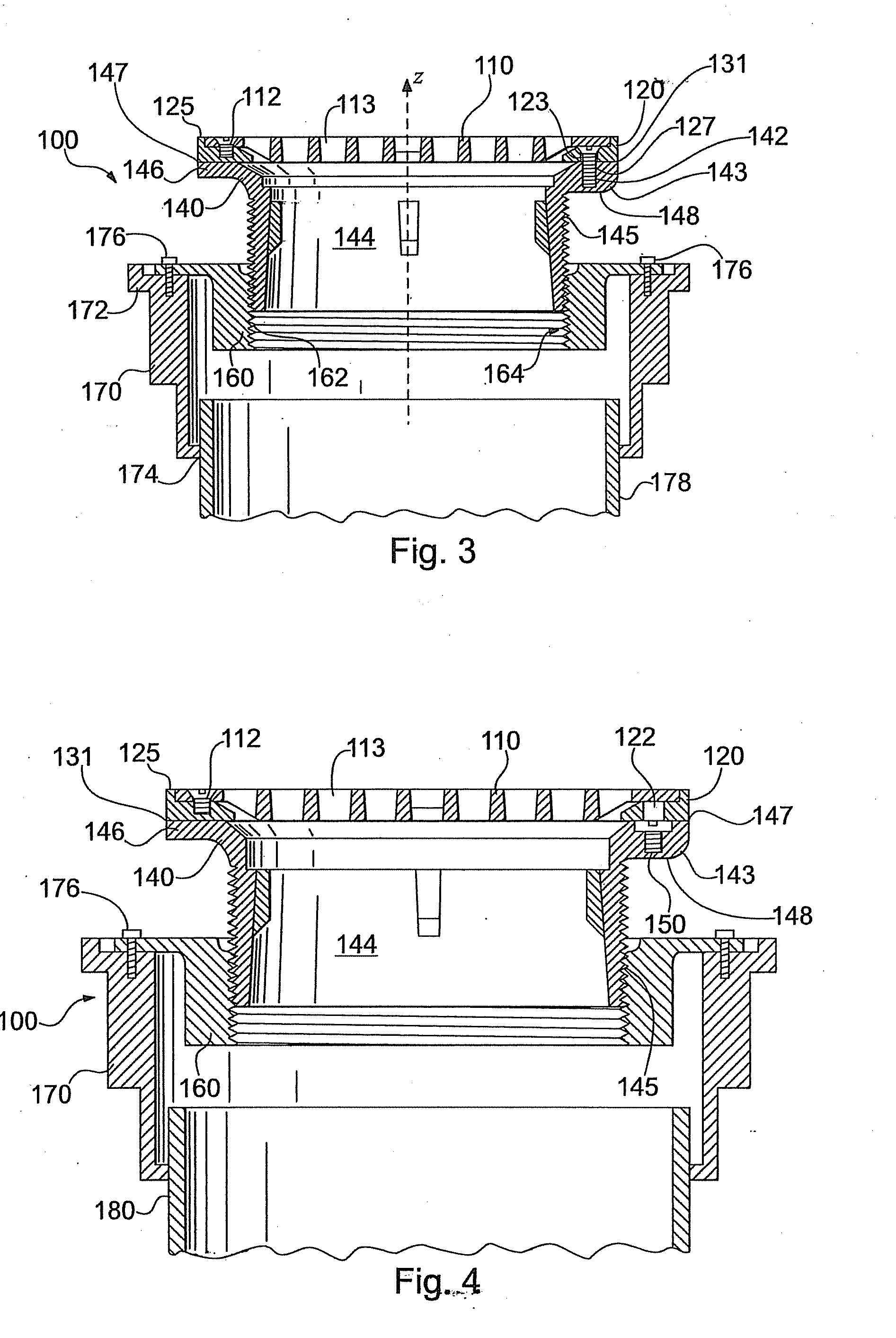
[0026]According to one embodiment, shown in FIGS. 3-12, a floor drain assembly 100 includes a top plate 110, a frame 120, a head 140, a collar 160, and a lower body 170.

[0027]Referring to FIGS. 5 and 7, the top plate 110 is a circular strainer and defines a plurality of openings 111 and a plurality of flow passages 113. The flow passages 113 permit the flow of fluid therethrough, but prevent the passage of solids of a particular siz...


PUM

PropertyMeasurementUnit
perimeteraaaaaaaaaa
diameteraaaaaaaaaa
heightaaaaaaaaaa

Abstract

A floor drain includes a head having a top surface, a leveling member, and a frame having a top surface and a bottom surface. The bottom surface of the frame is positioned adjacent the top surface of the head. The leveling member is positioned between the head and the bottom surface of the frame and is displaceable relative to the head in a first direction. A method of leveling a floor drain with a floor surface is also disclosed.

Description

CROSS REFERENCE TO RELATED APPLICATIONS[0001]This application claims the benefit of U.S. Provisional Application No. 61 / 034,639, filed Mar. 7, 2008, the entire contents of which are hereby incorporated by reference.BACKGROUND OF THE INVENTION[0002]1. Field of the Invention[0003]The present invention relates to floor drains, more particularly, to floor drains having a leveling mechanism.[0004]2. Description of Related Art[0005]A floor drain is used to funnel liquids from a floor surface into a drain pipe. The floor drain typically has a grate attached to the top drain to allow liquid to flow through the drain, but prevent larger solid objects from entering the floor drain. A particular type of floor drain known as “an adjustable floor drain”, as shown in FIGS. 1 and 2, employs a strainer 10, a head 20, a membrane clamp collar 30, and a lower body 40. The head 20 has a long threaded shank 22 that allows the head 20 to be adjusted upwardly and downwardly via a mating thread 32 in the m...

Claims


Application Information

Patent Timeline
Patent Type & Authority Applications(United States)
IPC IPC(8): G01M19/00E03F9/00G01M99/00
CPCE03F5/0407Y10T29/49778E04G23/02E03F2005/0413Y10T137/6988
Inventor WROBLEWSKI, DOUGLAS R.NICOLIA, CARL R.STEFFAN, JONATHANMARINI, MARK
Owner ZURN INDS
Why Eureka
Try Eureka