Optical system for batwing distribution

an optical system and batwing technology, applied in the field of radiation distribution systems, can solve the problems that the optical system of batwing used for incandescent and discharge lamps is not designed for use with leds

Active Publication Date: 2009-09-10
IDEAL IND LIGHTING LLC
View PDF48 Cites 169 Cited by
  • Summary
  • Abstract
  • Description
  • Claims
  • Application Information

AI Technical Summary

Problems solved by technology

The batwing optical systems used for incandescent an

Method used


Image

  • Optical system for batwing distribution
  • Optical system for batwing distribution
  • Optical system for batwing distribution

Examples


Embodiment Construction

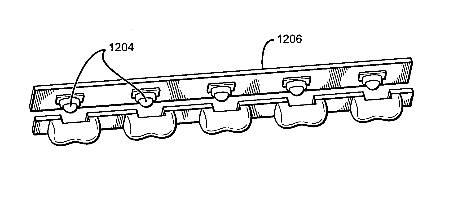
[0032]Embodiments of the present invention as claimed provide a radiation distribution system that generates a batwing distribution of luminous intensity. The system is particularly suited for use with LEDs and LED arrays. One or more light sources are positioned beneath a specially shaped lens that substantially envelopes the source(s). The shape of the lens is similar to a half peanut shell, sliced along the longer direction (i.e., the x-direction). At least one elongated reflective surface is positioned proximate to the lens and parallel to an axis running through center of the lens in the longer direction. In one embodiment two such elongated reflective surfaces are placed facing each other on opposite sides of the lens.

[0033]The light emitted from the source interacts with the enveloping lens first. The lens is made from an optically transmissive dielectric material. A dielectric interface formed by the boundary of the lens and the ambient material causes the light rays to be r...


PUM


Abstract

A radiation distribution system designed to produce a batwing distribution. The system may be used with radiative sources emitting in the visible spectrum or in other spectra. The system comprises a specially shaped lens disposed over a radiative source, such as an LED, for example. The lens and source are arranged between two reflector bodies, both of which have an elongated reflective surface that faces the source. The reflector bodies each have two different reflective surfaces that face outward and away from each other. The lens and both reflective surfaces work in concert to redirect a portion of the emitted radiation to create the desired batwing distribution. Several sources may be arranged linearly between a single pair of reflector bodies on a common surface to create a linear array of sources. Likewise, multiple linear arrays may be combined to form a two-dimensional array. In the two-dimensional configuration, linear arrays of sources are disposed on both sides of a reflector body, so that both of the reflective surfaces are utilized.

Description

BACKGROUND OF THE INVENTION[0001]1. Field of the Invention[0002]Embodiments of the present invention relate to radiation distribution systems, including optical systems that produce a batwing-type light distribution pattern.[0003]2. Description of the Related Art[0004]Many lighting applications require a fixture that produces a batwing-type distribution of light. The term “batwing” refers to a light distribution whose luminous intensity is greater along a direction at a significant angle relative to the main axis of distribution rather than along a direction parallel to the main axis. The desirability of a batwing distribution is evident in many lighting applications, including, for example, roadway lighting in which most of the light should be distributed in a direction parallel to the roadway.[0005]FIG. 1a shows various types of roadway illumination patterns named with a convention used by the Illuminating Engineering Society (IES). As shown, there are five common types of roadway...

Claims


Application Information

Patent Timeline
IPC IPC(8): F21V7/00G02B17/00G21G4/00A61N5/06H01L33/54
CPCF21S4/008F21V5/007F21V5/04F21V13/04F21V29/004F21W2131/103F21V29/763F21Y2103/003F21Y2105/001G02B27/095H01L33/54F21V29/505F21V29/71F21Y2101/02F21S4/28F21Y2103/10F21Y2105/10F21Y2115/10
Inventor JACOBSON, BENJAMIN A.GENGELBACH, ROBERT D.MEDENDORP, JR., NICHOLAS W.ROBERTS, LAWRENCEPERRY, JOHN
Owner IDEAL IND LIGHTING LLC
Why Eureka
Try Eureka