Powered Orthotic Device and Method of Using Same

a technology of orthotics and powered devices, applied in the field of orthotics, can solve the problems of affecting the function of one or more limbs, affecting the ability of patients to perform constructive, functional rehabilitation exercises without assistance, and affecting the ability of patients to control or strength the afflicted limb or limb so severely,

Active Publication Date: 2009-09-10
MYOMO
View PDF38 Cites 108 Cited by
  • Summary
  • Abstract
  • Description
  • Claims
  • Application Information

AI Technical Summary

Benefits of technology

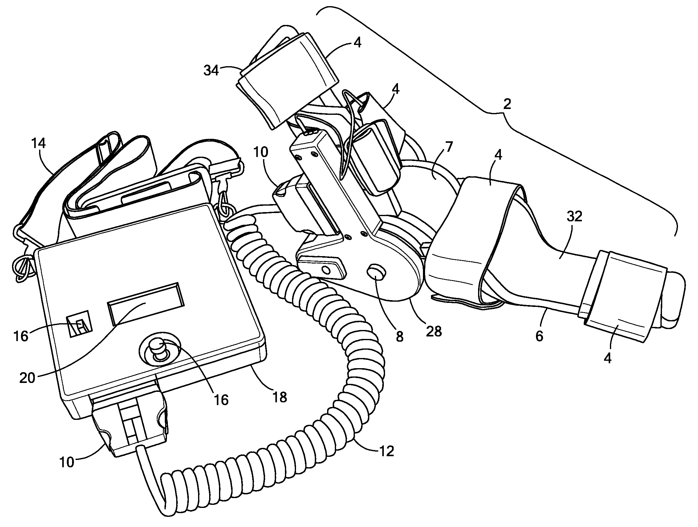
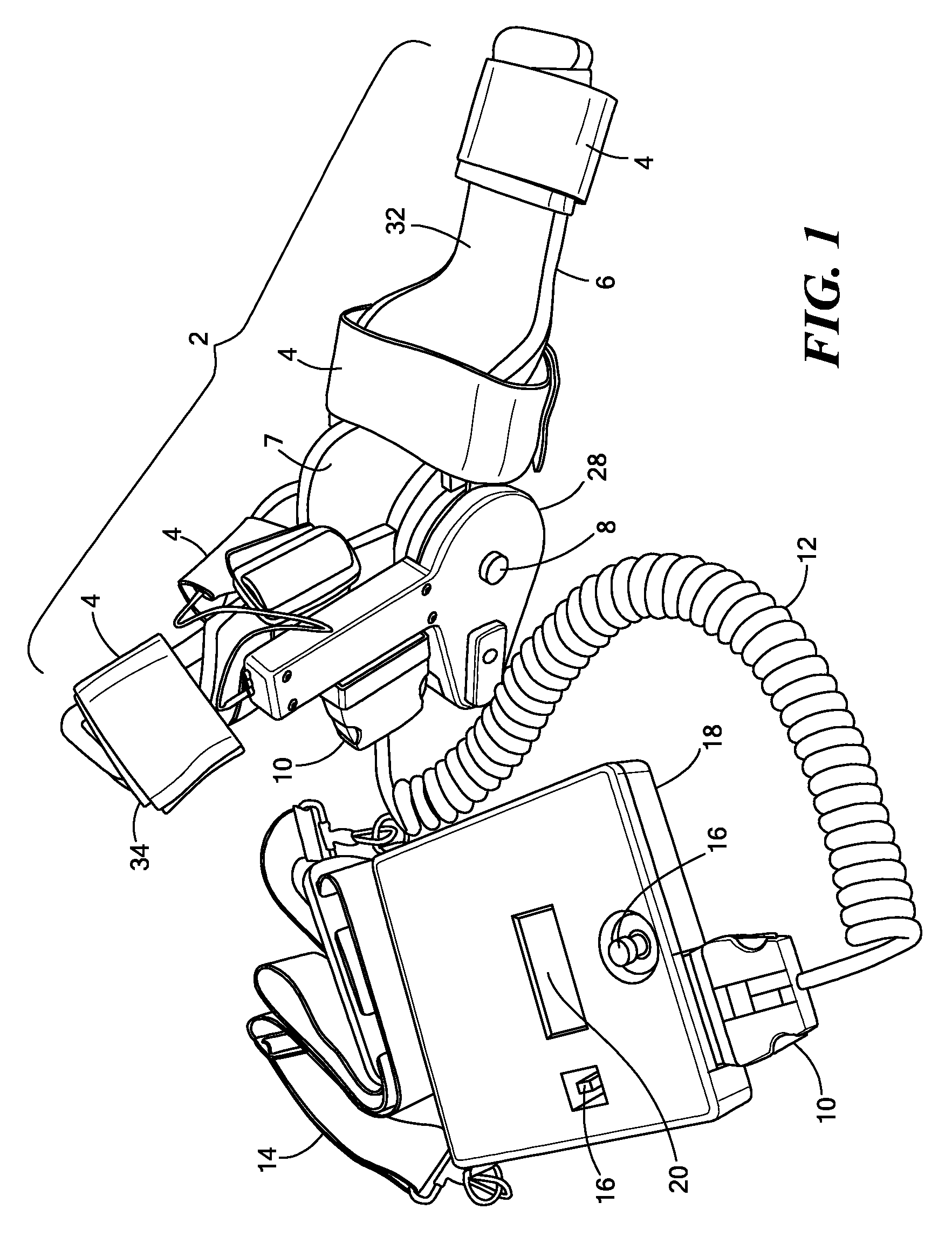
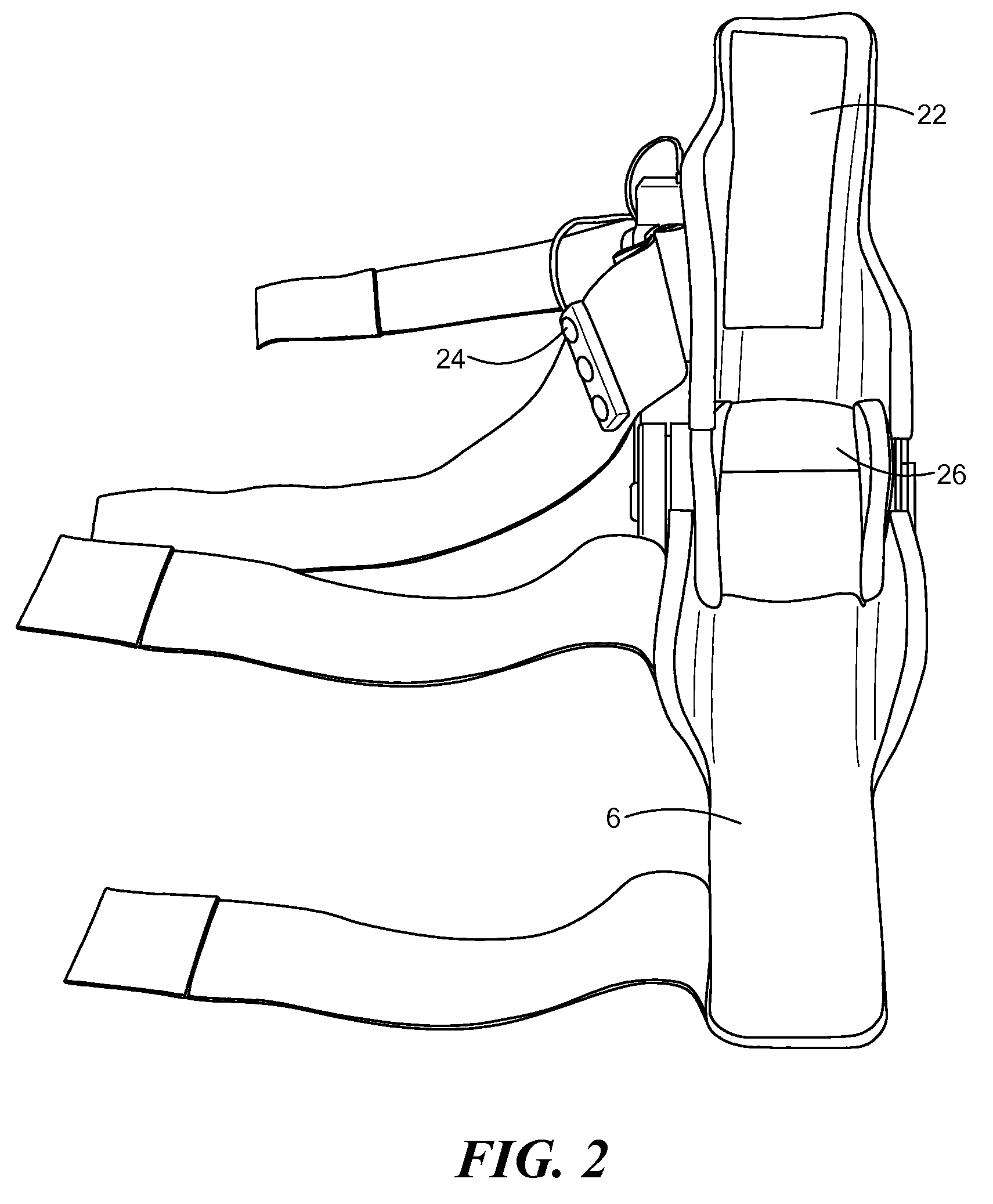
[0004]In accordance with one embodiment of the invention, a powered orthotic system includes a wearable component having a brace with a first section and a second section. The first and second sections are coupled to each other at a pivot. Each section is adapted to be removably attached to a corresponding first and second limb segment such that the pivot is proximate to a joint between each limb segment. The first and the second sections are movable with respect to each other to define flexion and extension directions. The wearable component also includes an electromyographic sensor, an electrically powered actuator assembly in communication with the electromyographic sensor, and a controller in communication with the actuator assembly that provides system parameters to control operation of the actuator assembly. The actuator assembly is coupled to the first and the second sections so as to apply a force that moves the first and the second sections in the flexion and/or extension directions and the force is based on signals from the electromyographic sensor. The actuator assembly is positioned proximate to the pivot. The system also includes a control unit in communication with the wearable component. The control unit includes a processor that modifies the system parameters in the controller and a user interface, in communication with the processor, that permits user selection of the system parameters.
[0005]In related embodiments, the wearable component may further include a user interface, in communication with the controller, that permits user selection of operational modes of the wearable component. The wearable component's user interface may allow for a single input that causes a plurality of system parameters to be modified in the controller. The wearable component may further include a battery coupled to the electrically powered actuator assembly. The control unit and the wearable component may be in wireless communication with each other. The system may further include one or more additional wearable components, each additional wearable component in communication with the control unit. The system may further include one or more additional control units, each additional control unit in communication with one or more of the wearable components. The wearable component may further include memory, coupled to the controller, that stores the system parameters.

Problems solved by technology

The result can be impaired or lost function in one or more limbs.
Following neuromuscular trauma, however, the control or strength in the afflicted limb or limbs

Method used


Image

  • Powered Orthotic Device and Method of Using Same
  • Powered Orthotic Device and Method of Using Same
  • Powered Orthotic Device and Method of Using Same

Examples


examples

[0133]An asymmetric EMG-controlled orthotic device in accordance with embodiments described herein was built and used in clinical trials on healthy individuals and on stroke survivors. The control algorithms proved effective in both enabling stroke survivors to control the device, and in promoting rehabilitation of the afflicted joint(s). FIGS. 31 and 32 are graphs showing rehabilitation progress of the subjects in the clinical trial, according to industry-standard rehabilitation scales (Fugl-Meyer and Ashworth).

[0134]Embodiments of an EMG-controlled orthotic device may be used in a variety of ways and with various protocols as a rehabilitation or functional aid. For example, rehabilitative exercise regimes may include the execution of familiar and / or functional tasks, or components thereof, to enhance the user's functional capacity. To this end, a subject's functional capabilities may be first assessed and classified into various levels without the device on. For example, three lev...


PUM


Abstract

A powered orthotic system includes a wearable component having a brace with a first section and a second section. The first and second sections are coupled to each other at a pivot. Each section is adapted to be removably attached to a corresponding first and second limb segment such that the pivot is proximate to a joint between each limb segment. The first and the second sections are movable with respect to each other to define flexion and extension directions. The wearable component also includes an electromyographic sensor, an electrically powered actuator assembly in communication with the electromyographic sensor, and a controller in communication with the actuator assembly that provides system parameters to control operation of the actuator assembly. The actuator assembly is coupled to the first and the second sections so as to apply a force that moves the first and the second sections in the flexion and/or extension directions and the force is based on signals from the electromyographic sensor. The actuator assembly is positioned proximate to the pivot. The system also includes a control unit in communication with the wearable component. The control unit includes a processor that modifies the system parameters in the controller and a user interface, in communication with the processor, that permits user selection of the system parameters.

Description

CROSS-REFERENCE TO RELATED APPLICATIONS[0001]This patent application claims priority to U.S. Provisional Patent Application No. 61 / 037,556 filed Mar. 18, 2008, and is a continuation-in-part application of U.S. patent application Ser. No. 11 / 857,881 filed Sep. 19, 2007, which claims priority to U.S. Provisional Patent Application No. 60 / 826,188 filed Sep. 19, 2006 and U.S. Provisional Patent Application No. 60 / 889,773 filed Feb. 14, 2007, the disclosures of which are incorporated by reference herein in their entirety.FIELD OF THE INVENTION[0002]The invention generally relates to orthotic devices and, more particularly, the invention relates to powered orthotic devices and methods of using same for rehabilitation or functional aids.BACKGROUND OF THE INVENTION[0003]Stroke, brain injury, and other neuromuscular trauma survivors are often left with hemipareisis, or severe weakness in certain parts of the body. The result can be impaired or lost function in one or more limbs. It has been ...

Claims


Application Information

Patent Timeline
IPC IPC(8): A61F5/00
CPCA61F5/0127A61H1/008A61H1/02A61F5/013
Inventor MCBEAN, JOHN M.NARENDRAN, KAILAS
Owner MYOMO
Why Eureka
Try Eureka