Analyzing 2-D Surface and/or Borehole Seismic Data to Locate Subsurface Diffractors

a seismic data and subsurface technology, applied in the field of seismic data processing, can solve the problems of not being able to provide reliable knowledge about the unpredictable structure of the line, and not being generally suited to 3-d seismic migration imaging

Inactive Publication Date: 2009-09-10
LANDMARK GRAPHICS
View PDF14 Cites 14 Cited by
  • Summary
  • Abstract
  • Description
  • Claims
  • Application Information

AI Technical Summary

Benefits of technology

[0020]In another set of embodiments, a method for locating subsurface diffractors may involve receiving 2-D seismic data that includes one or more 2-D seismic lines, where each of the 2-D seismic lines includes a plurality of seismic traces and a respective plurality of trace positions. The trace positions specify where the seismic traces were obtained.
[0021]The method may also involve, for each hypothetical diffractor location L in a set of hypothetical diffractor locations, analyzing at least a subset of the seismic traces of the one or more 2-D seismic lines to compute a value VL indicating an extent to which those seismic traces contain diffraction arrivals that are consistent with the hypothetical diffractor location. Each of the hypothetical diffractor locations may satisfy a condition that none of the trace positions of the one or more 2-D seismic lines lies within a 3-D neighborhood of diameter 200 meters centered on the hypothetical diffractor location.

Problems solved by technology

However, this acquisition has interline spacing measured in kilometers, and thus, is not generally suited to 3-D seismic migration imaging.
This does not provide reliable knowledge about unpredictable structure between the lines, precisely the information that dense 3-D acquisition and imaging provides.
Commonly, such unpredictable structures form the flow barriers sealing hydrocarbons into reservoirs.

Method used


Image

  • Analyzing 2-D Surface and/or Borehole Seismic Data to Locate Subsurface Diffractors
  • Analyzing 2-D Surface and/or Borehole Seismic Data to Locate Subsurface Diffractors
  • Analyzing 2-D Surface and/or Borehole Seismic Data to Locate Subsurface Diffractors

Examples


Embodiment Construction

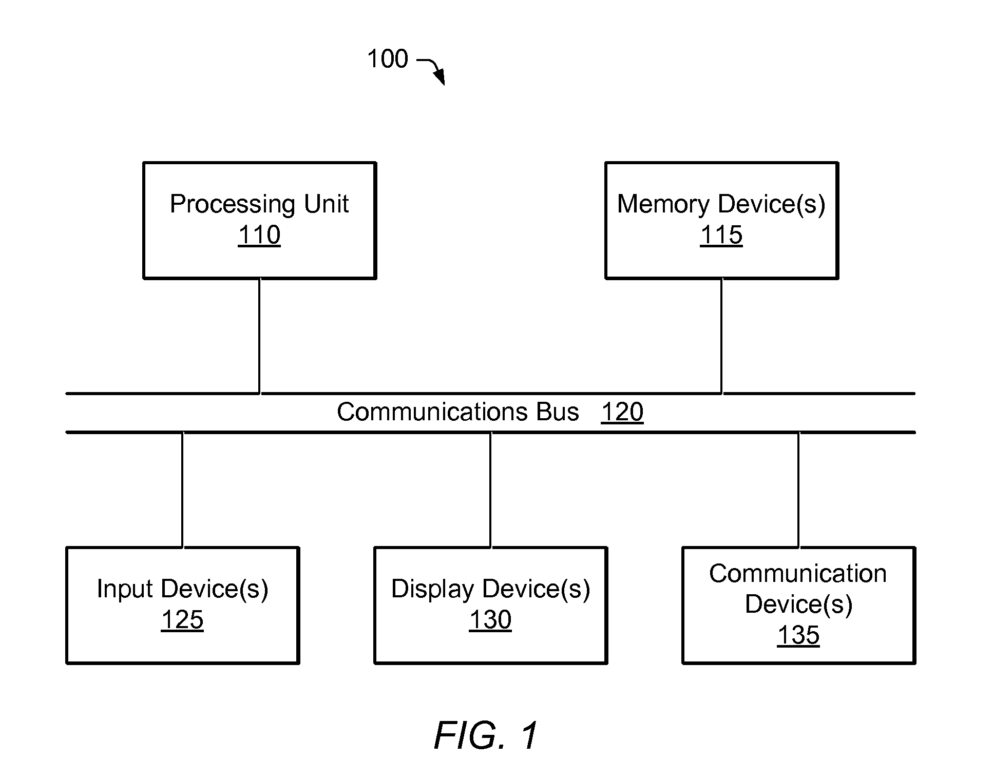
[0039]The present invention may be realized in any of various forms. For example, in some embodiments, the present invention may be realized as a computer-implemented method, a computer-accessible memory medium, or a computer system. In other embodiments, the present invention may be realized using one or more custom designed hardware devices such as ASICs or FPGA's.

[0040]A memory medium is a medium configured for the storage and retrieval of information. Examples of memory media include: various kinds of semiconductor memory such as RAM and ROM; various kinds of magnetic media such as magnetic disk, tape, strip, and film; various kinds of optical media such as CD-ROM and DVD-ROM; various media based on the storage of electrical charge and / or other physical quantities; media fabricated using various lithographic techniques; etc.

[0041]A computer-accessible memory medium is a memory medium that stores program instructions and / or data, where the program instructions are executable by a...


PUM


Abstract

A system and method for locating subsurface diffractors. The method operates on two-dimensional (2-D) seismic data that includes one or more 2-D seismic lines. The 2-D seismic data may be preprocessed to enhance diffracted energy. For each hypothetical diffractor location in a set of hypothetical diffractor locations, the method involves analyzing at least a subset of the seismic traces of the one or more 2-D seismic lines, in order to compute a value indicating an extent to which those seismic traces contain diffraction arrivals consistent with the hypothetical diffractor location. The method may further involve generating, storing and displaying an image (or map) based on the computed values. The image may illustrate areas of high, intermediate and low diffraction, and may be used to assess the formation.

Description

RELATED APPLICATION DATA[0001]This application is a continuation in part of U.S. application Ser. No. 11 / 674,526 filed on Feb. 13, 2007, entitled “Performing 3-D Scatterer Imaging From 2-D Seismic Data”, invented by Stewart A. Levin, which is hereby incorporated by reference in its entirety.FIELD OF THE INVENTION[0002]The present invention generally relates to seismic data processing, and more particularly, to a mechanism for locating subsurface diffractors based on an analysis of seismic data.DESCRIPTION OF THE RELATED ART[0003]Seismic exploration involves the study of underground formations and structures. In seismic exploration, one or more sources of seismic energy may emit waves into a region of interest, such as a formation. These waves enter the formation and may be scattered, e.g., by reflection and / or refraction. One or more sensors are employed to capture the scattered waves, thereby generating seismic data. (The signal captured by a sensor in response to a single shot or ...

Claims


Application Information

Patent Timeline
Patent Type & Authority Applications(United States)
IPC IPC(8): G06G7/48
CPCG01V1/301
Inventor LEVIN, STEWART A.
Owner LANDMARK GRAPHICS
Why Eureka
Try Eureka