
Hand-held device for removing an enclosure from a container

a container and hand-held technology, applied in the field of container removal, can solve the problems of pain or discomfort for users, drawbacks of this type of device, and enclosures or lids that are difficult for end-users or consumers to remove from containers,

Inactive Publication Date: 2009-09-17
HAMILTON BEACH BRANDS
View PDF25 Cites 15 Cited by
  • Summary
  • Abstract
  • Description
  • Claims
  • Application Information

AI Technical Summary

Benefits of technology

[0006]Therefore, it would be desirable to create at least a partially automated hand-held device for removing enclosures or lids from containers that would allow a user to easily remove a lid or enclosure of a jar or other container without having to directly touch or grasp either the container or the enclosure. Specifically, it would be desirable to create a jar opener that provides a degree of “hands-free” operation. Further, it would be desirable to create a jar opener that uses the force and power of a motor to remove the lid from the jar without requiring additional energy or force from the user. Furthermore, it would be desirable to create a user friendly, compact and portable jar opener that can be easily and conveniently stored and / or transported.

Problems solved by technology

However, such tightly secured enclosures or lids often become difficult for the end-user or consumer to remove from the container.
However, there are drawbacks to this type of device.
For instance, the jar openers require a solid or stable location to mount the jar opener, and the user is required to directly hold the jar or container body which may cause pain or discomfort to the user.
Further, individuals with arthritis or other similar symptoms may have difficulty using such jar openers.
However, there are disadvantages to these types of jar openers.
Specifically, these types of openers require that the user directly hold the jar or container as well as the lid, which often causes discomfort or pain to certain individuals.

Method used


Image

  • Hand-held device for removing an enclosure from a container
  • Hand-held device for removing an enclosure from a container
  • Hand-held device for removing an enclosure from a container

Examples


Embodiment Construction

[0024]Certain terminology is used in the following description for convenience only, and is not limiting. The words “right,”“left,”“upper,” and “lower” designate directions in the drawings to which reference is made. The terms “a,”“an” and “the” are not limited to one element but should be read as meaning “at least one.” The terminology includes the words above specifically mentioned, derivatives thereof, and words of similar import.

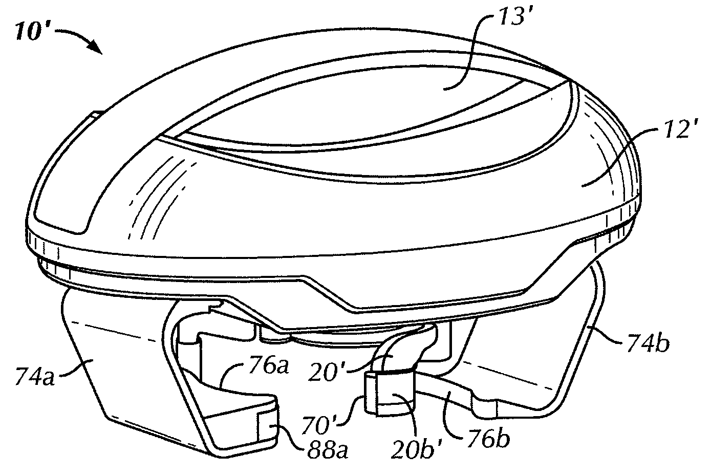
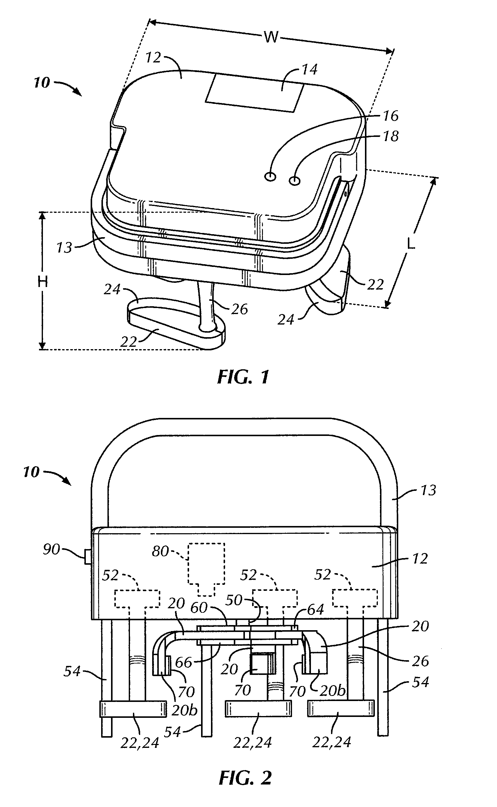
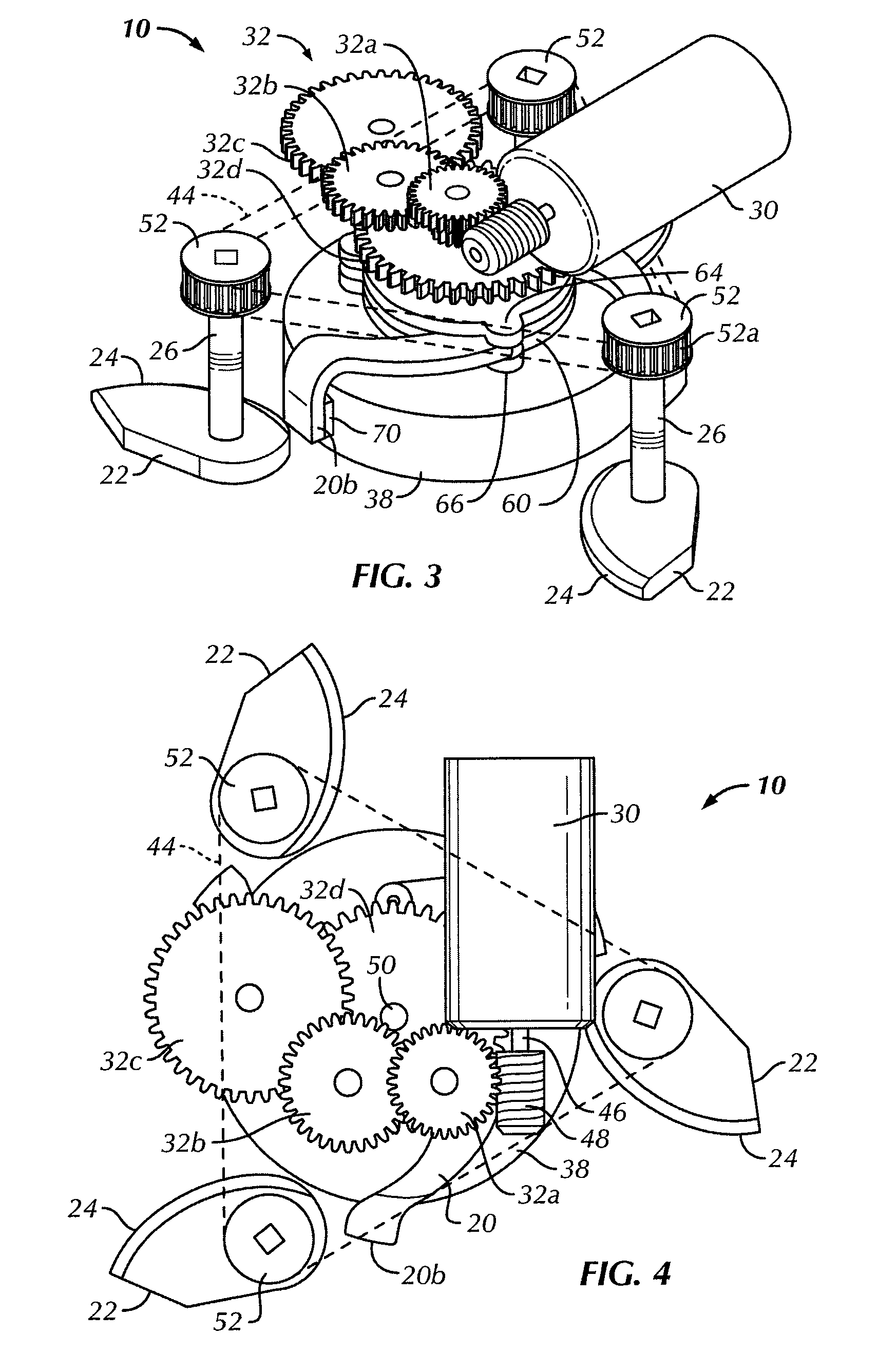
[0025]Referring to the drawings in detail, wherein like numerals indicate like elements throughout, there is shown in FIGS. 1-6 a first preferred embodiment of a hand-held device for removing an enclosure from a container, such as a jar opener, indicated generally at 10, in accordance with the present invention. The jar opener 10 is preferably an automated household or kitchen appliance for rotatably removing an enclosure or lid 38 (FIGS. 3-6) from a jar (not shown) or other container (not shown) that provides the user with a degree of “hands-free” opera...


PUM


Abstract

A device for removing an enclosure from a container includes a housing at least partially enclosing at least one reversible motor and at least two spaced-apart cams. The cams are rotatable in a first rotational direction in which the cams grasp the container and in a second rotational direction in which the cams are rotated a predetermined distance away from the container. A wrench disk is operatively connected to and rotatable by the at least one motor. At least two spaced-apart wrenches are pivotally attached to the wrench disk for removably grasping the enclosure. Operation of the motor in a first direction rotates the wrench disk in a first rotational direction causing the wrenches to grasp and rotate the enclosure relative to the container. Operation of the motor in a second direction rotates the wrench disk in a second rotational direction causing the wrenches to rotate a predetermined distance away from the enclosure.

Description

CROSS-REFERENCE TO RELATED APPLICATIONS[0001]The present application claims the benefit of U.S. Provisional Patent Application No. 61 / 036,332, filed Mar. 13, 2008 and entitled “Device for Removing an Enclosure from a Container.”BACKGROUND OF THE INVENTION[0002]This invention generally relates to the removal of an enclosure from a container and, more particularly, to a jar opener or other similar hand-held device that rotatably removes a lid or other type of enclosure device from a jar or similar container.[0003]It is well known that placing foodstuff into an enclosed jar or other container is advantageous to the preservation of the foodstuff. Specifically, producers, distributors and manufactures of various types of foodstuff often fasten the enclosure or lid to ajar or other container very tightly (e.g., air tight) to assure that the contents within the container are preserved throughout the shipment and shelf-life of the foodstuff. This process is advantageous because it allows fo...

Claims


Application Information

Patent Timeline
IPC IPC(8): B67B7/00B67B7/14
CPCB67B7/182
Inventor GARMAN, MICHAELSTAMPER, III, GEORGE W.SONG, BRANDONROTH, ROBERT H.HOGUE, KENBEST, BOB
Owner HAMILTON BEACH BRANDS
Learn More