Surgery Assisting Apparatus and Treatment Assisting Apparatus

Inactive Publication Date: 2009-09-17
OLYMPUS MEDICAL SYST CORP
View PDF3 Cites 57 Cited by
  • Summary
  • Abstract
  • Description
  • Claims
  • Application Information

AI Technical Summary

Problems solved by technology

However, the luminal organs are often hidden by the diseased organ, so that there are problems that visual confirm of the luminal organs is difficult and procedures can not be smoothly performed.
However, treatment has been conventionally performed while merely observing an endoscope image on the monitor and the like, so that there has been a problem that the region of the treated tissue

Method used


Image

  • Surgery Assisting Apparatus and Treatment Assisting Apparatus
  • Surgery Assisting Apparatus and Treatment Assisting Apparatus
  • Surgery Assisting Apparatus and Treatment Assisting Apparatus

Examples


first embodiment

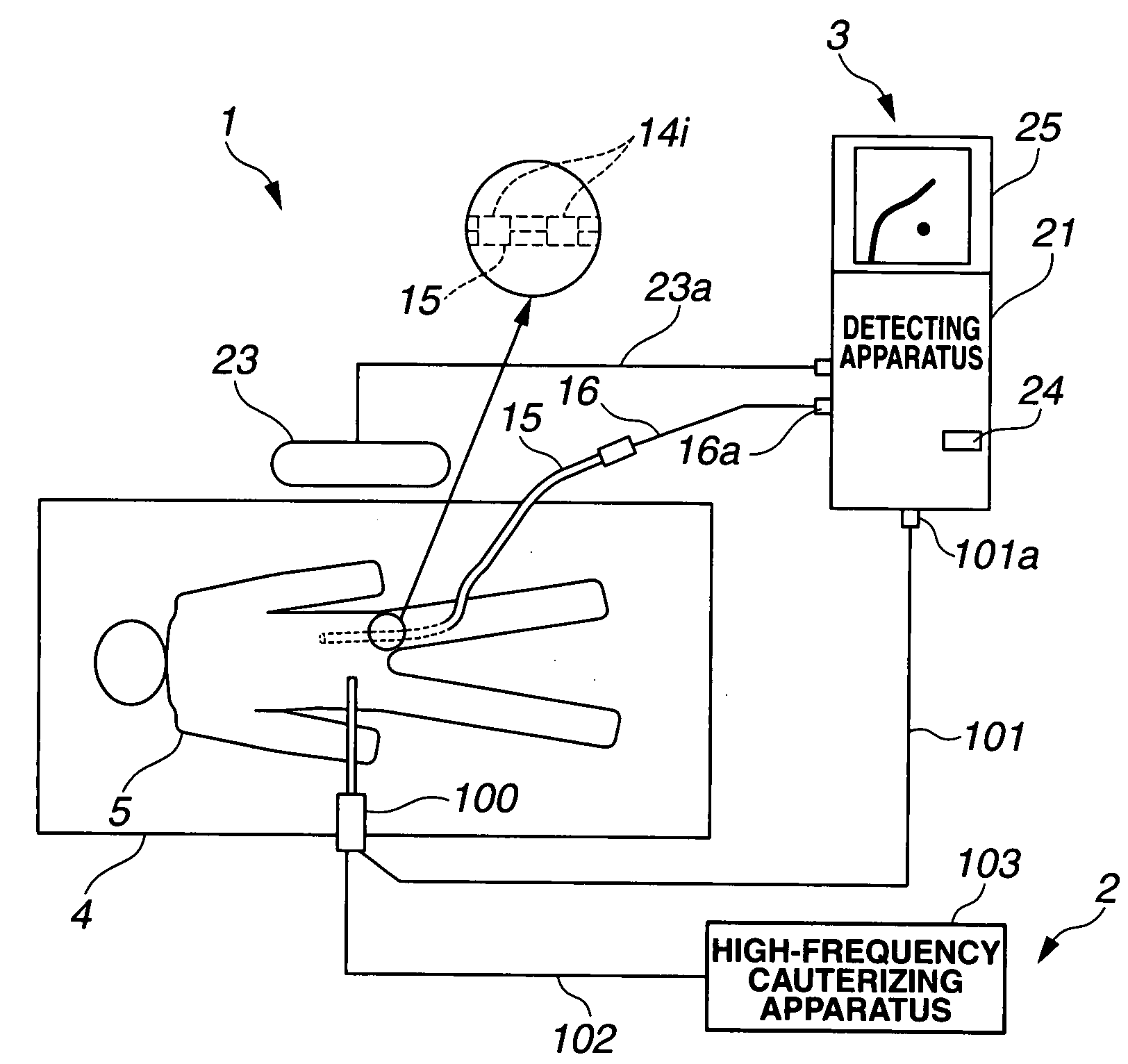
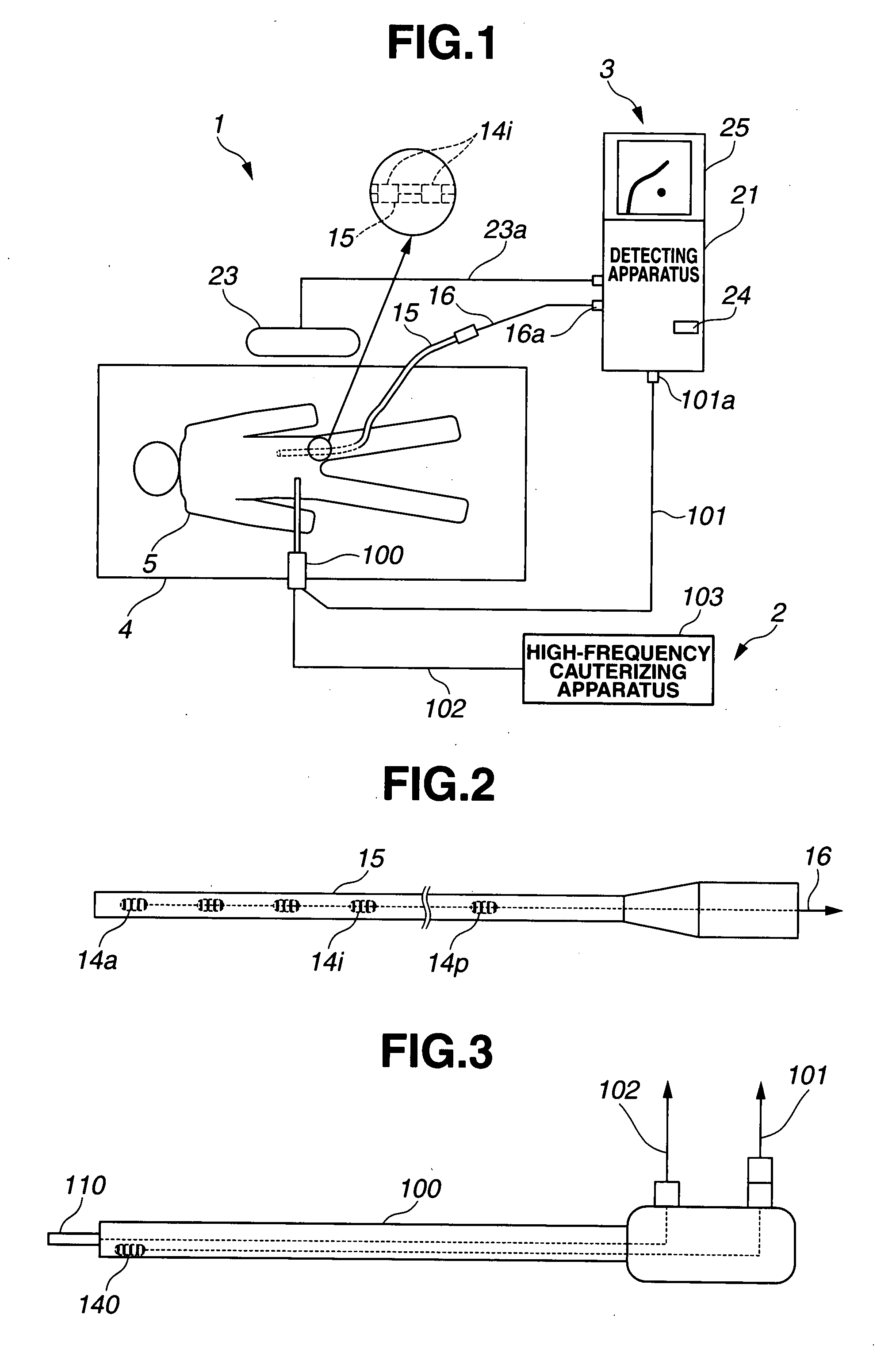
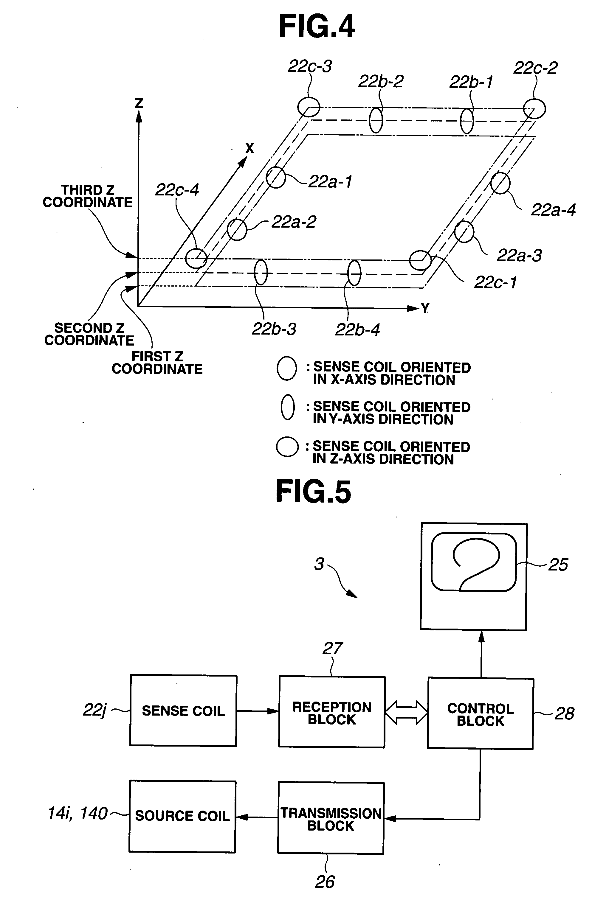
[0073]FIGS. 1 to 12 relate to the first embodiment of the present invention, in which: FIG. 1 is a configurational view showing a configuration of a surgery system; FIG. 2 is a view showing a configuration of a probe of FIG. 1; FIG. 3 is a view showing a configuration of a surgical tool of FIG. 1; FIG. 4 is a view showing a disposition example of coils incorporated in a coil unit of FIG. 1; FIG. 5 is a configurational view showing a configuration of a luminal organ shape detecting apparatus of FIG. 1; FIG. 6 is a view showing configurations of a reception block and a control block of FIG. 5; FIG. 7 is a view showing a detailed configuration of the reception block of FIG. 5; FIG. 8 is a timing view showing a working of a two-port memory and the like of FIG. 6; FIG. 9 is a flowchart describing an action of the luminal organ shape detecting apparatus of FIG. 1; FIG. 10 is an explanatory view describing processings of FIG. 9; FIG. 1I is a view showing a configuration of a first modifica...

second embodiment

[0101]FIGS. 13 to 17 relate to the second embodiment of the present invention, in which: FIG. 13 is a view showing a configuration of a surgical tool; FIG. 14 is a flowchart describing an action of the luminal organ shape detecting apparatus when using the surgical tool of FIG. 13; FIG. 15 is a first explanatory view describing processings of FIG. 14; FIG. 16 is a second explanatory view describing the processings of FIG. 14; and FIG. 17 is a third explanatory view describing the processings of FIG. 14.

[0102]The second embodiment is almost the same as the first embodiment, so that only the different points will be described. The same components are attached with the same reference symbols, and the descriptions thereof will be omitted.

[0103]As shown in FIG. 13, the surgical tool 100 of the present embodiment has, in the vicinity of the distal end thereof at which the electrode 110 is provided, a plurality of, or at least two source coils 140, 141 disposed along a longitudinal axis. B...

third embodiment

[0114]FIGS. 18 and 19 relate to the third embodiment of the present invention, in which FIG. 18 is a configurational view showing a configuration of a surgery system and FIG. 19 is a flowchart describing an action of a luminal organ shape detecting apparatus of FIG. 18.

[0115]The third embodiment is almost the same as the second embodiment, so that only the different points will be described. The same components are attached with the same reference symbols, and the descriptions thereof will be omitted.

[0116]In the present embodiment, as shown in FIG. 18, the detecting apparatus 21 of the luminal organ shape detecting apparatus 3 controls the output of the high-frequency cauterizing apparatus 103 via a control cable 300, depending on the proximity state between the blood vessel and the surgical tool 100. Other configurations are the same as those in the second embodiment.

[0117]Description will be made on an action of the present embodiment thus configured.

[0118]As shown in FIG. 19, st...


PUM


Abstract

According to the invention, an endoscope system as a surgery assisting apparatus includes a surgery apparatus for performing treatment by abdominal operation procedure on a region to be treated in a body of a patient, and a luminal organ shape detecting apparatus used for assisting (supporting) the abdominal operation procedure. The luminal organ shape detecting apparatus is used as blood vessel position notifying means when procedure is performed by inserting a probe as a luminal organ insertion probe into a blood vessel, for example. This allows the luminal organ irrespective of the treatment to be easily and surely detected and enables a smooth procedure to be performed.

Description

TECHNICAL FIELD[0001]The present invention relates to a surgery assisting apparatus and a treatment assisting apparatus which assist a surgery using a magnetic-field generating element and a magnetic-field detecting element.BACKGROUND ART[0002]In recent years, there has been used an endoscope shape detecting apparatus which detects a shape and the like of an endoscope inserted, for example, into a body cavity using a magnetic-field generating element and a magnetic-field detecting element, and displays the detected shape by display means.[0003]For example, Japanese Unexamined Patent Application Publications No. 2003-245243 and No. 2003-290129 disclose an apparatus which detects the shape of an endoscope using magnetic fields, and displays the detected shape of the endoscope. In these conventional examples, a plurality of magnetic-field generating elements disposed at a predetermined interval in an insertion portion of the endoscope which is inserted in a body are driven to generate ...

Claims


Application Information

Patent Timeline
IPC IPC(8): A61B1/00A61B5/05
CPCA61B5/06A61B5/064A61B18/1402A61B2019/5297A61B19/5225A61B2019/5454A61B2019/5214A61B19/40A61B90/04A61B2090/3612A61B2090/368A61B90/37A61B2090/3954
Inventor ONODA, FUMIYUKINIWA, HIROSHISATO, MINORUODA, TOMOHIKOMIYOSHI, YOSHITAKAMIYAKE, KENSUKEAIZAWA, CHIEKO
Owner OLYMPUS MEDICAL SYST CORP
Why Eureka
Try Eureka