
Cover assemblies for covering objects

a technology for covering objects and assemblies, applied in the field of covering assemblies, can solve the problems of dirt being transferred from the cover to the object being covered, cumbersome and unsightly, and difficult to fit on the known cover, and achieve the effect of convenient and rapid deployment of the covering member

Inactive Publication Date: 2009-09-24
JLM ACCESSORIES
View PDF5 Cites 20 Cited by
  • Summary
  • Abstract
  • Description
  • Claims
  • Application Information

AI Technical Summary

Benefits of technology

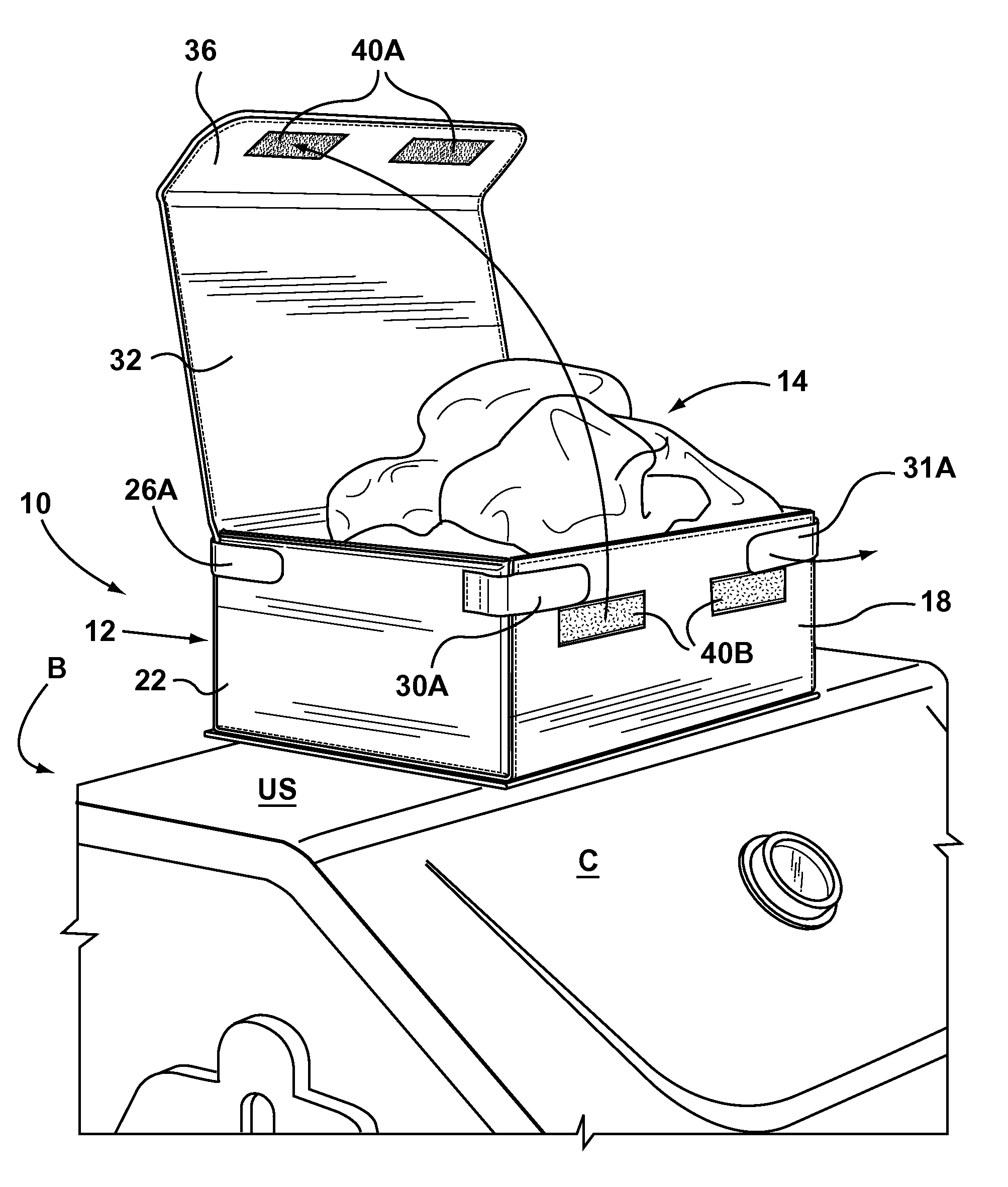
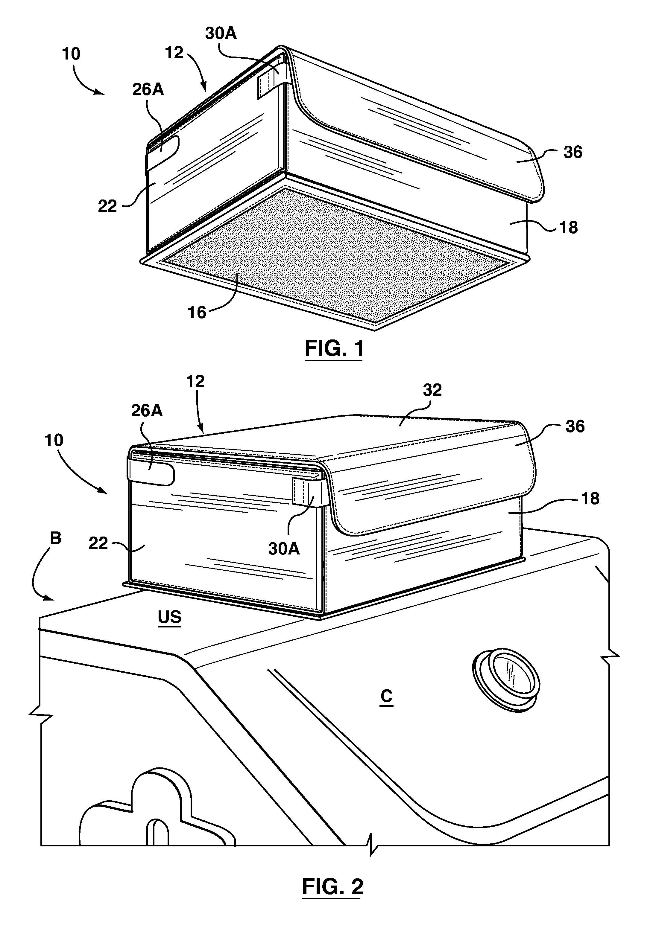
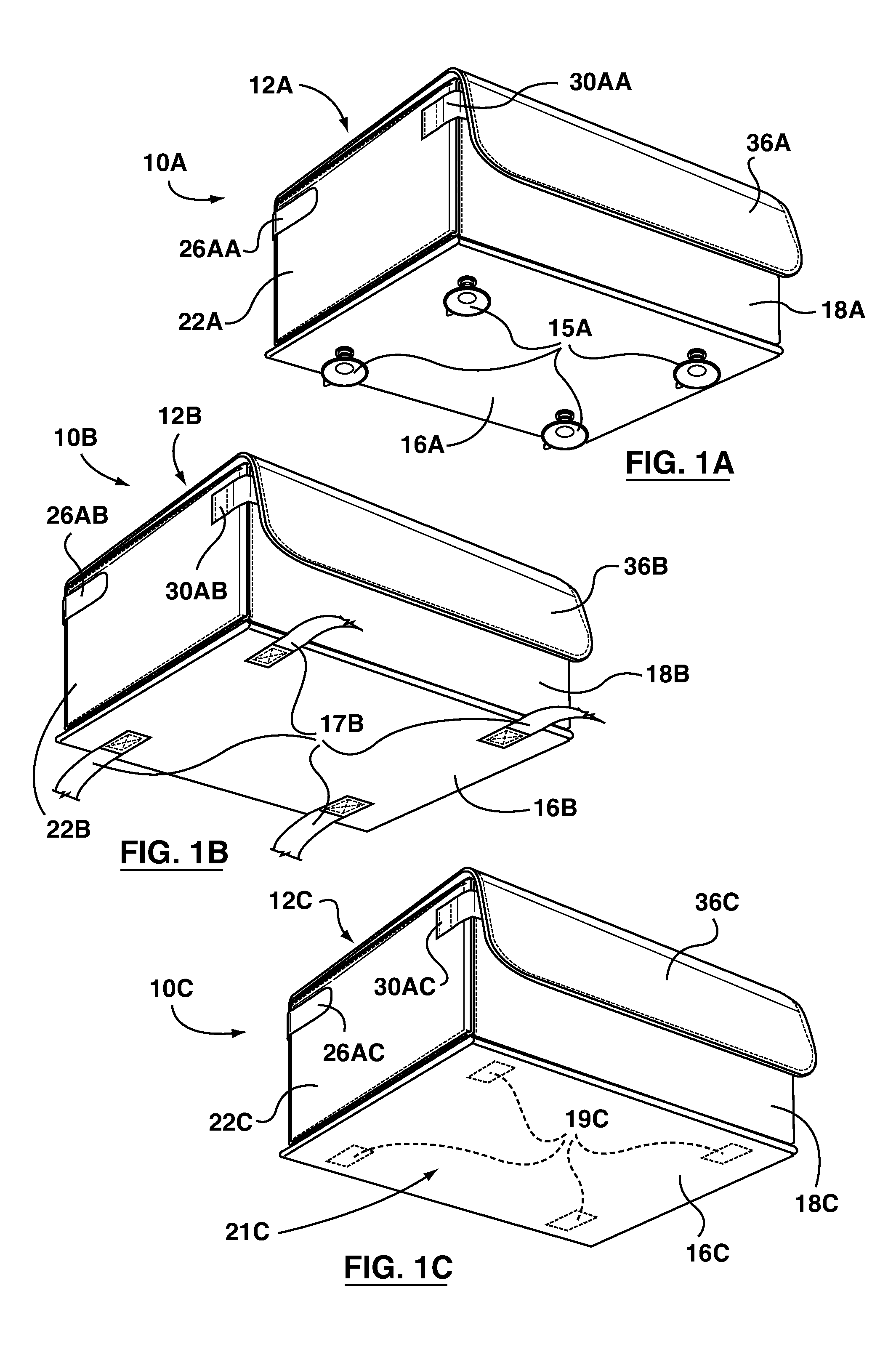
[0004]According to an aspect of the present invention, a cover assembly is provided. The cover assembly includes a covering member for covering a notional object, and a container for containing the covering member when the covering member is not in use. The covering member has an object-covering shape, and the container is selectively configurable in a containment configuration in which the covering member can be housed within the container, and a deployment configuration from which the covering member may be deployed to cover the notional object. The container has a defined orientation relative to the notional object to be covered, and the covering member is secured to the container at a predetermined position of the covering member and in alignment with the defined orientation of the container. As a result, when the container is placed in a predetermined position on the notional object to be covered, corresponding to the predetermined position of the covering member, with the defined orientation of the container matching the orientation of the notional object to be covered, the object-covering shape of the covering member will be aligned with the shape of the notional object to be covered. This facilitates easy and rapid deployment of the covering member to cover the object. In addition, the container may be provided with an anchor for maintaining the container in position on the notional object to be covered during deployment of the covering member. The anchor may be, for example, a high-friction material, one or more suction cups, one or more straps, or one or more magnets.

Problems solved by technology

However, known covers are often difficult to fit onto and to remove from the object to be covered, and are also often cumbersome and unsightly when not in use.
In addition, during the deployment and removal process, the covers are often dragged across the ground, which is unsanitary and can lead to dirt being transferred from the cover to the object being covered.

Method used


Image

  • Cover assemblies for covering objects
  • Cover assemblies for covering objects
  • Cover assemblies for covering objects

Examples


first embodiment

[0136]In another embodiment (not shown), the walls may be held in the erected configuration by an actuating member in the form of a cord extending around the upper ends of the walls and passing through apertures therein. The cord may be provided with a slider which retains the walls in the erected configuration, and can be slid back to permit the container walls to fall outwardly to the collapsed configuration to expose the covering member 14. Conversely, to return the container to the erected configuration, a user would pull the cord and slide the slider along the cord to abut the front wall of the container. A lid similar to lid 32 in the first embodiment may be provided. An example of such an arrangement is shown in U.S. Patent Application Publication No. 20070283946 A1, which is co-owned by the assignee hereof.

[0137]In the exemplary embodiments 10, 10A, 10B and 10C so far described, the respective container 12, 12A, 12B, 12C has taken the form of a rectangular parallelepiped. Ot...

embodiment 1900

[0139]The container 1902 is a clamshell container, comprising a first clamshell portion 1908 and a second clamshell portion 1910 pivotingly secured to one another at respective inner edges 1912, 1914 thereof. In the illustrated embodiment 1900, the first clamshell portion 1908 and the second clamshell portion 1910 are made from a flexible fabric material, and are pivotingly secured to one another by way of a living hinge 1916 (FIG. 20). The closed configuration of the clamshell container 1902 is defined by the first clamshell portion 1908 and the second clamshell portion 1910 being in facing relation to one another as shown as shown in FIGS. 18 and 19; this closed configuration serves as a containment configuration for containing the covering member 2104. By pivoting the clamshell portions 1908, 1910 away from one another about the living hinge 1916, the container 1902 can be moved into an open configuration to permit deployment of the covering member 2104. The container includes a ...

third embodiment

[0187]In FIGS. 30E and 30F, a cover assembly for covering a notional watercraft 3050 according to an aspect of the present invention, is indicated generally at 3000E. The cover assembly 3000E comprises a container in the form of an upright bag 3002E and a covering member 3004E. The covering member 3004E has a size and shape corresponding to those of the notional watercraft 3050 to be covered, but aside from this difference is substantially identical to the cover assembly 2900E. The predetermined position of the covering member 3004E, which is secured to the container 3002E, is the portion that will cover the seat of the notional watercraft 3050, and the predetermined position of the notional watercraft 3050 is the seat thereof. In FIG. 30E, the cover assembly 3000E is shown anchored on the seat of the notional watercraft 3050 with the upright bag 3002E in the closed configuration and thereby containing the covering member 3004E. FIG. 30D shows the cover assembly 3000E with the cover...


PUM


Abstract

A cover assembly comprises a covering member having an object-covering shape, and a container for containing the covering member. The container has a containment configuration and a deployment configuration, and has a defined orientation relative to a notional object to be covered. The container also has an anchor for non-invasively maintaining the container in position on the notional object to be covered. The covering member is secured to the container at a predetermined position of the covering member and in alignment with the defined orientation of the container. Placement of the container at a predetermined position of the notional object to be covered corresponding to the predetermined position of the covering member, with the defined orientation of the container matching the orientation of the notional object to be covered, aligns the object-covering shape of the covering member with a shape of the notional object to be covered.

Description

CROSS-REFERENCE TO RELATED APPLICATIONS[0001]This application is a Continuation-in-Part of U.S. application Ser. No. 11 / 448,801, filed Jun. 7, 2006, entitled “BARBEQUE COVER ASSEMBLY,” and a Continuation-in-Part of U.S. application Ser. No. 12,333,496, filed Dec. 12, 2008, entitled “BARBEQUE COVER ASSEMBLY,” all of which are incorporated herein by reference in their entirety.FIELD OF INVENTION[0002]This invention relates to cover assemblies, and more particularly to cover assemblies for use in covering various objects.BACKGROUND OF THE INVENTION[0003]It is often advantageous to position a cover over certain objects when those objects are not in use. For example, barbecues, vehicles and outdoor furniture may be covered when not in use, to protect them from the elements. As such, many different kinds of covers are known for covering various objects. However, known covers are often difficult to fit onto and to remove from the object to be covered, and are also often cumbersome and unsi...

Claims


Application Information

Patent Timeline
Patent Type & Authority Applications(United States)
IPC IPC(8): B65D65/02
CPCA47J37/0786
Inventor MARUZZO, WALTER FIORE
Owner JLM ACCESSORIES
Learn More