Electromagnetic and Magnetostatic Shield to Perform Measurements Ahead of the Drill Bit

a magnetostatic shield and drill bit technology, applied in the field of electromagnetically inducible well logging, can solve the problems of reducing the sensitivity of the measured em field, introducing a metal drill pipe close, and limited tool group

Active Publication Date: 2009-09-24
BAKER HUGHES INC
View PDF9 Cites 54 Cited by
  • Summary
  • Abstract
  • Description
  • Claims
  • Application Information

AI Technical Summary

Benefits of technology

[0013]One embodiment of the disclosure is a method of using an electromagnetic instrument in a borehole in an earth formation. The method includes changing a current through a transmitter on an electromagnetic instrument in a borehole and inducing a current in the earth formation; receiving a first transient signal resulting from the induced current in a first receiver and a second transient signal in a second receiver on the instrument, the first transient signal and the second transient signal including effects of a conductive body of the instrument; and using the first signal and the second signal for estimating a distance to an interface in the earth formation, the estimating being substantially unaffected by the conductive body.
[0014]Another embodiment of the disclosure is an apparatus configured to evaluate an earth formation. The apparatus includes an electromagnetic instrument having a conductive body configured to be conveyed in a borehole; at least one processor configured to change a current in a transmitter on the instrument; a first receiver configured to receive a first transient signal resulting from current induced in the formation responsi

Problems solved by technology

This group of tools is naturally limited by, among other things, their applicability to only high-resistivity formations and the power available downhole.
The major problem associated with the MWD environment is the introduction of a metal drill pipe close to the area being measured.
This pipe produces a very strong response and significantly reduces the sensitivity of the measured EM field to the effects of formation resistivities and remote boundaries.
However, the sensitivity of such a tool to remote bo

Method used


Image

  • Electromagnetic and Magnetostatic Shield to Perform Measurements Ahead of the Drill Bit
  • Electromagnetic and Magnetostatic Shield to Perform Measurements Ahead of the Drill Bit
  • Electromagnetic and Magnetostatic Shield to Perform Measurements Ahead of the Drill Bit

Examples


first embodiment

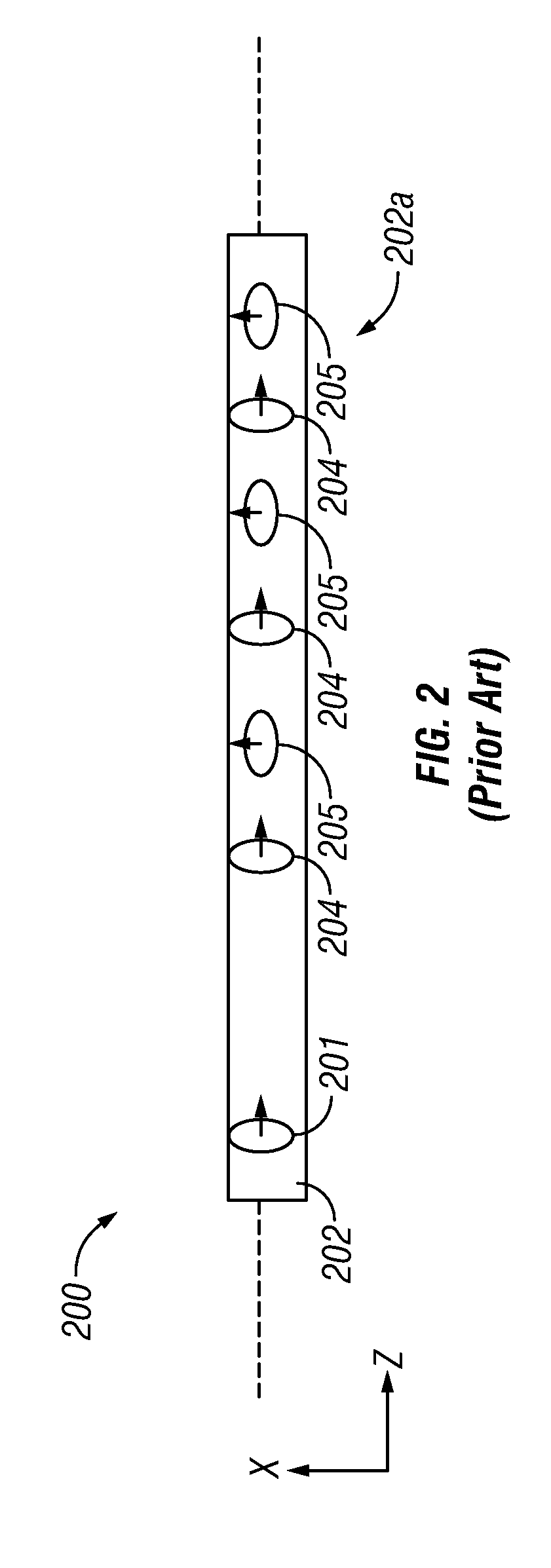
[0041]Although FIG. 2 illustrates one configuration of the transmitter 201 and receiver(s) 204, 205, a variety of transmitter-receiver configurations can be used in various illustrative embodiments of the present disclosure. In the MWD transient tool 200, the Z-oriented transmitter coil 201 can be positioned along the damping portion 202, and a receiver coil pair 205-204 comprising an X-oriented coil 205 and a Z-oriented receiver coil 204 may be axially displaced from the Z-oriented transmitter coil 201. The receiver pair 205-204 may typically be placed at a distance of from about 0 m to about 10 m from the transmitter coil 201, also along the damping portion 202. A transmitter-receiver distance less than approximately 2 m from the transmitter coil 201 may further enable geosteering. The term geosteering refers to control of the drilling direction of the BHA based upon determined distances from an interface in the earth formation. Typically, in geosteering, it is desirable to mainta...

third embodiment

[0053]In order to boost a resolution of transient system further a third embodiment that utilizes a combination of a three coil bucking system and copper shield. A copper shield is assumed to be covering whole space between transmitter and receivers (about 7 m long) and being thick enough (couple mm) to prevent penetration of eddy currents into the steel pipe. Further information about the copper shield may be found in Itskovich '381.

[0054]To prove an effectiveness of the copper shield we performed mathematical modeling of the bucked response for the system with copper shield surrounded by formation described earlier. Modeling is performed for the water-oil boundary placed at 8 m from the transient system, which represents more of a challenge than a model with the boundary at 4 m, since as was pointed out earlier the larger the distance to the boundary, the later is the time when this boundary can be detected.

[0055]Results for 1 and 2 m-bucked receivers are presented in FIG. 15, whi...


PUM


Abstract

A transmitter on a bottomhole assembly (BHA) is used for generating a transient electromagnetic signal in an earth formation. A pair of receivers on the BHA receive signals that are indicative of formation resistivity and distances to bed boundaries. A time dependent calibration factor or a time-independent calibration factor may be used to combine the two received signals and estimate the distance to bed boundaries that are unaffected by the drill conductive body. Further improvement can be obtained by using copper shielding.

Description

CROSS-REFERENCES TO RELATED APPLICATIONS[0001]This application claims priority from U.S. Provisional Patent Application Ser. No. 61 / 037,930 filed on Mar. 19, 2008.BACKGROUND OF THE DISCLOSURE[0002]1. Field of the Disclosure[0003]The disclosure relates to the field of electromagnetic induction well logging. More specifically, the present disclosure is a method of reducing effects of conductive drill pipes on signals in transient electromagnetic measurements for evaluation of earth formations ahead of the drill bit.[0004]2. Description of the Related Art[0005]Electromagnetic induction resistivity instruments can be used to determine the electrical conductivity of earth formations surrounding a wellbore. An electromagnetic induction well logging instrument is described, for example, in U.S. Pat. No. 5,452,761 issued to Beard et al. The instrument described in the Beard '761 patent includes a transmitter coil and a plurality of receiver coils positioned at axially spaced apart locations...

Claims


Application Information

Patent Timeline
IPC IPC(8): G01V3/18
CPCG01V3/28G01V3/08G01V3/10G01V3/26G01V3/38
Inventor ITSKOVICH, GREGORY B.CHEMALI, ROLAND E.WANG, TSILI
Owner BAKER HUGHES INC
Why Eureka
Try Eureka