
Method and support structure for integrating audio and video components

a technology for audio and video components, applied in the direction of stereophonic systems, stereophonic arrangments, electrical apparatus, etc., can solve the problems of complicated consequences, significant confusion, and disadvantages of integrated systems, and achieve the effect of simplifying the conventional practice of providing a number of components

Inactive Publication Date: 2009-09-24
BEAUCHAMP TODD
View PDF7 Cites 31 Cited by
  • Summary
  • Abstract
  • Description
  • Claims
  • Application Information

AI Technical Summary

Benefits of technology

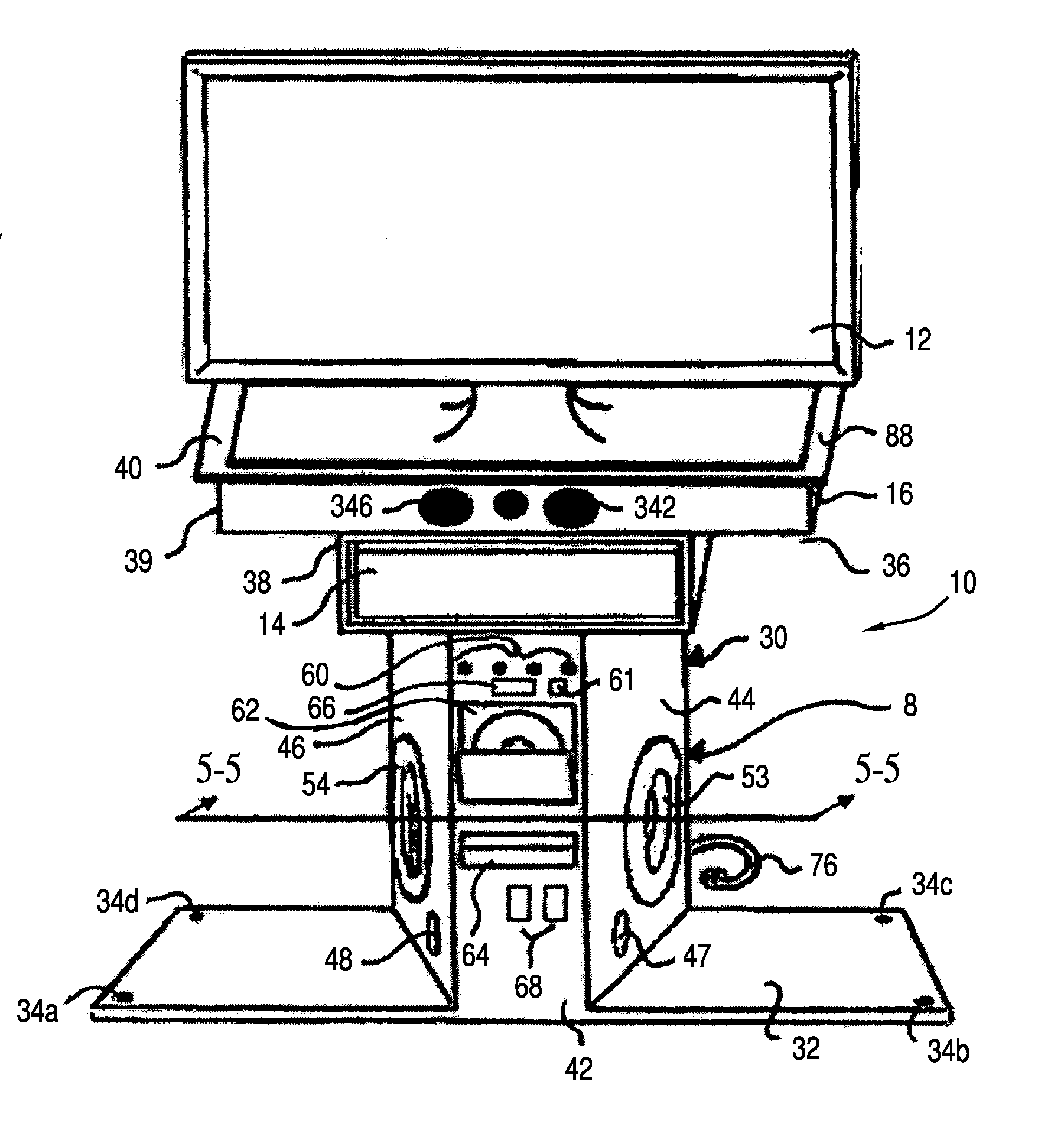
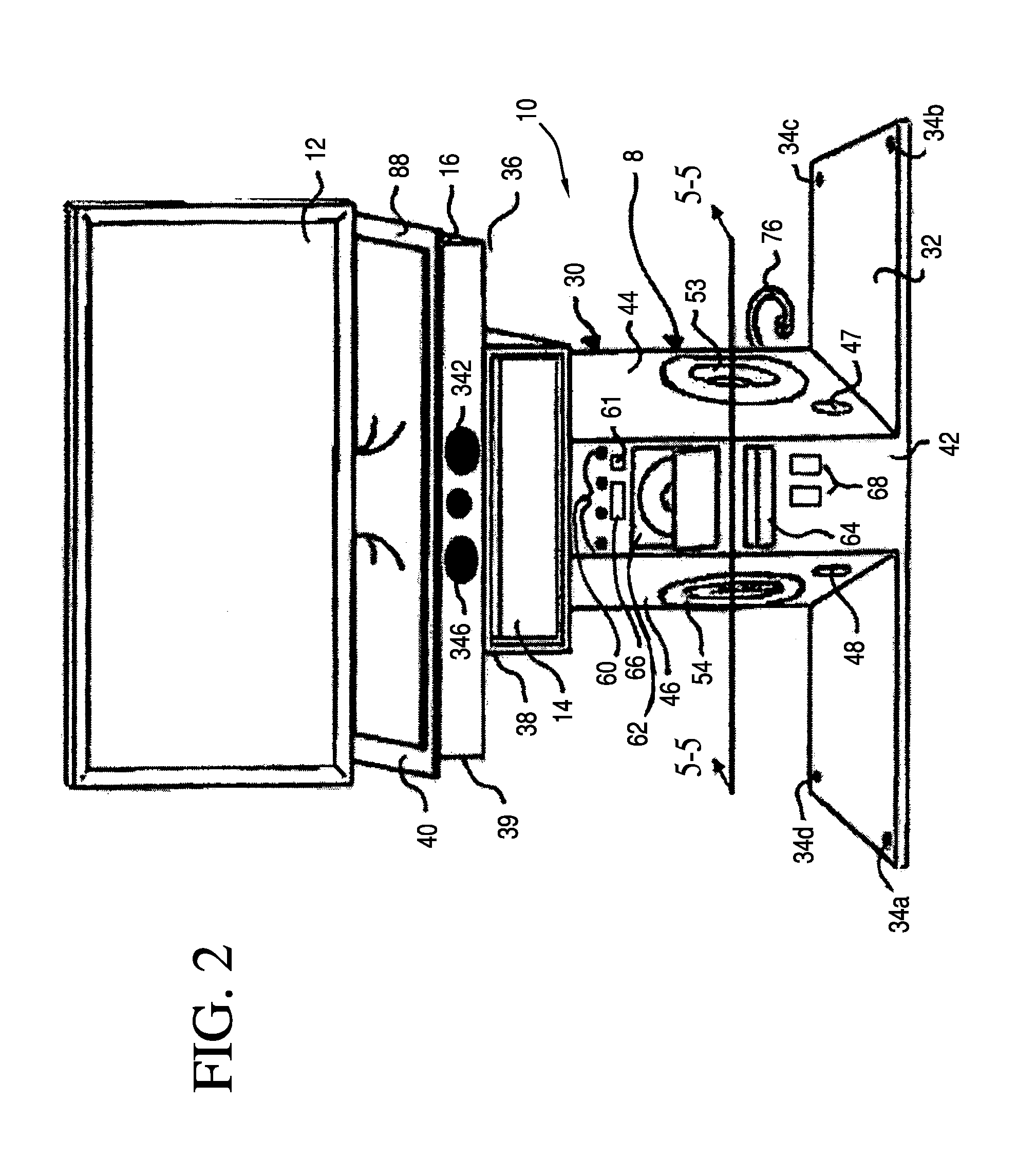
[0017]In accordance with the present invention, a simple, attractive and technically advanced structure and method for integrating and operating a home entertainment system provides a plurality of modular configurations, each integrated in a single enclosure. The component modules may share a common power supply and heat dissipation components. The enclosure comprises a stand on which a video display unit such as a television set may be supported. A support, such as a shelf, and an interface may be provided for a discrete component such as a cable box. A center channel speaker unit may be supported between the enclosure and the shelf.

Problems solved by technology

The many possible combinations of connections and settings for each component have lead to significant confusion.
Polk Audio, Bose and others have answered by integrating DVD players and amplifiers with speakers into a type of system known generically as the “home theater in a box.” But even these integrated systems have disadvantages.
The conventional practice of providing a number of components has complicating consequences.
This may result in a veritable “rat's nest” of wires behind the home entertainment system.
Technically unsophisticated users may require a great deal of time to make the proper interconnections.
In older homes, the total current draw of the different devices may provide a burden on an individual power circuit.
In other systems, combinations of modules that are functionally well matched may have an aesthetically displeasing appearance due to dissimilarity in external design.
The prior art has not provided a satisfactory solution for many users.
This approach entails the expense of transmitters and receivers.
The provision of a number of wireless radio frequency sources requires use of a number of frequency bands or coding schemes, which increases system complexity.
Wireless units may also produce interference with other wireless units or with tuners and amplifiers in a system.
One disincentive for such integration is the mechanically deleterious effects on electronics modules of vibrations and heat generated when a subwoofer is energized.
Center channel speaker units have not been adequately integrated into stands and home entertainment units.
Size constraints of the center channel also constrain the level of acoustical power that can be supplied from the center channel.
The smaller center channels may not be capable of delivering the same high SPL levels of the subwoofer.
Therefore the power that the subwoofer is designed to provide must also be limited to stay at the lower SPL limits of the center channel.
If the subwoofer is not limited and continues to be played louder than the center channel, the bass may become overbearing and sound unnatural.
The total system performance either suffers by unnatural sound or limited maximum sound output depending on the system design.
Generally, it is difficult to obtain good performance from a small center channel speaker unit (as compared to a larger center channel speaker).
“Wife Acceptance Factor” and other constraints tend to limit both the size of the center channel speaker unit and the number of modules that can be stored on the shelves of the television stand.
The small speaker's limited audio output thus limits performance of the entire speaker array.
In smaller designs of center channel speakers, another commonly encountered drawback is that sound must be transmitted from speaker drivers into cabinet walls of the stand, causing further audio degradation.

Method used


Image

  • Method and support structure for integrating audio and video components
  • Method and support structure for integrating audio and video components
  • Method and support structure for integrating audio and video components

Examples


Embodiment Construction

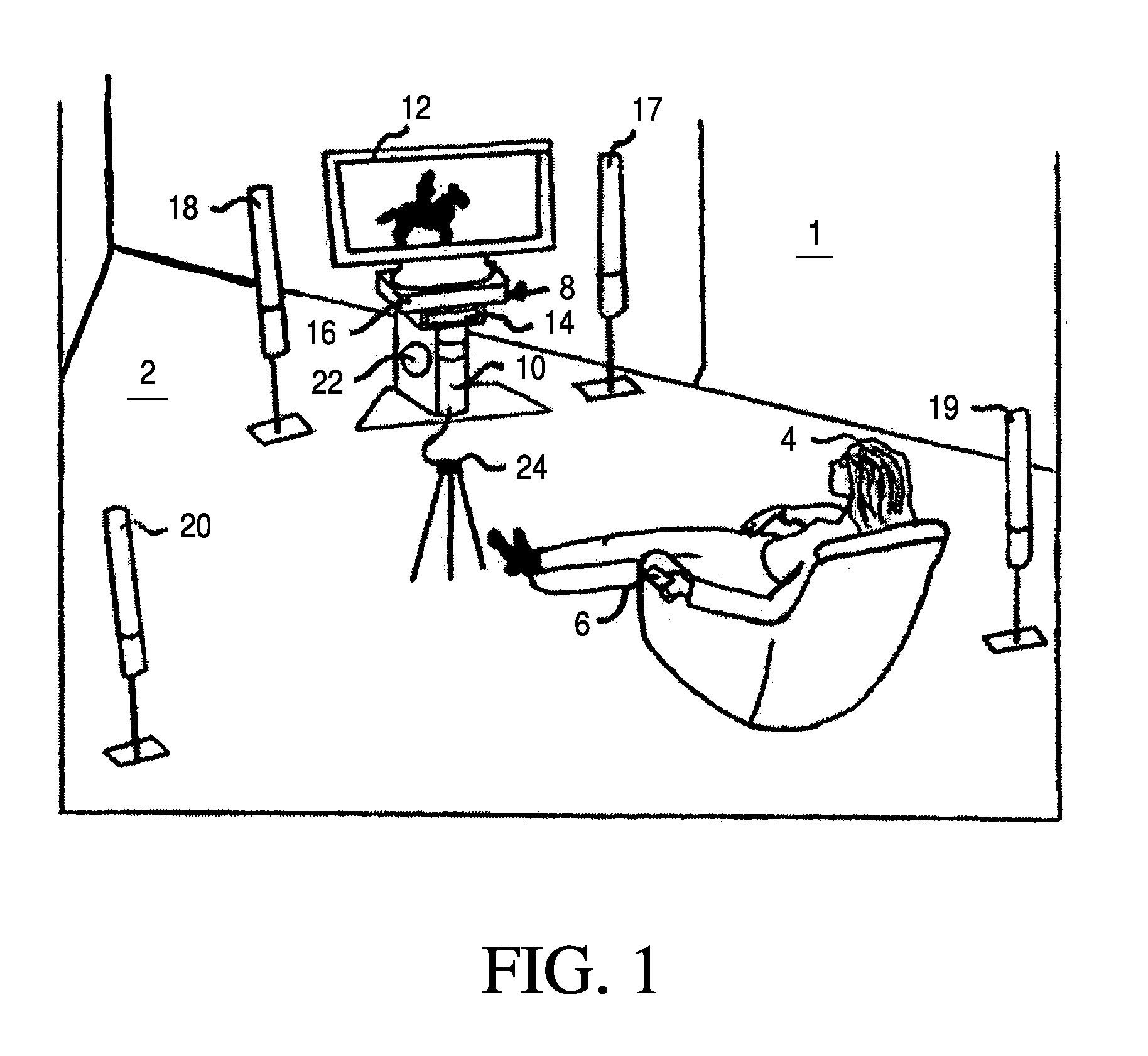
[0046]Referring to FIGS. 1-18, a home entertainment environment 1 located in a room 2 is described in general with respect to FIG. 1. A user 4 may utilize a remote control unit 6 to control operation. The home entertainment environment 1 comprises the apparatus, which creates an entertainment experience for the user 4. The home entertainment environment 1 comprises a home entertainment system 10 and may comprise a video display 12. The video display 12 may be part of a television set including tuners and an amplifier. Alternatively, the video display 12 could comprise a video monitor. The home entertainment system 10 is housed in a modular base 8. The home entertainment system 10 comprises components which provide different functions and which are integrated. Particular modules in the home entertainment unit 10 are described in further detail with respect to FIGS. 5 and 6. At the present time, commonly provided components include a radio tuner, digital video disc (DVD) player / record...


PUM


Abstract

A method and support structure for integrating audio and video components includes integrating a plurality of components having diverse functions, e.g., tuners, media player / recorders, amplifiers and a surround sound unit, into a single supportive enclosure configured as a unitary system rather than one with many boxes or modules requiring additional space. The modules may share a common power supply and heat dissipation components. The enclosure provides a stand to support a video display unit or a television set. A shelf support and an interface are optionally provided for a discrete component such as a cable box. In an alternative embodiment, the enclosure does not support a video display unit but houses a center channel speaker unit in a structure unitary with the enclosure.

Description

[0001]This application is a continuation-in-part and claims priority to (a) provisional patent application No. 60 / 632,187 filed Jan. 6, 2005 and to (b) utility patent application Ser. No. 11 / 325,485 filed Jan. 5, 2006, the entire disclosures of which are each incorporated herein by reference.BACKGROUND OF THE INVENTION[0002]1. Field of the Invention[0003]The present invention relates to audio and video home entertainment equipment typically configured for use in the home.[0004]2. Discussion of the Prior Art:[0005]Many home entertainment enthusiasts have configured audio and video playback systems including several components stacked on or under shelves, stands, carts, cabinets or tables, and these components are usually connected to one another with many signal cables and power cords. A system configured in this way typically includes components for receiving, detecting and demodulating audio and video signals, players for playing various forms of media, video displays and audio amp...

Claims


Application Information

Patent Timeline
Patent Type & Authority Applications(United States)
IPC IPC(8): H04R5/02
CPCH04S3/00H04R5/02
Inventor BEAUCHAMP, TODD
Owner BEAUCHAMP TODD
Learn More