
Blower

a blower and blower body technology, applied in the field of blowers, can solve the problems of deformation of the motor housing, difficulty in maintenance and repair of the blower, and easy damage to the start capacitor and the switch b>16/b>, and achieve the effect of convenient maintenance and repair

Inactive Publication Date: 2009-09-24
LIN JEN WEI
View PDF18 Cites 14 Cited by
  • Summary
  • Abstract
  • Description
  • Claims
  • Application Information

AI Technical Summary

Benefits of technology

"The invention provides a blower that overcomes the disadvantages of prior art. The blower has a housing with a driver housing and a fan housing, a fan blade unit, a driving device, a start capacitor, a switch device, and a power source device. The power source device is connected electrically to the switch device. The housing unit also has a mounting recess covered by a removable cover plate. The start capacitor and the switch device are connected electrically to the driving device at the mounting recess. This design allows for easy maintenance and repair of the blower in case of malfunctions."

Problems solved by technology

The start capacitor and the switch 16 are easily damaged.
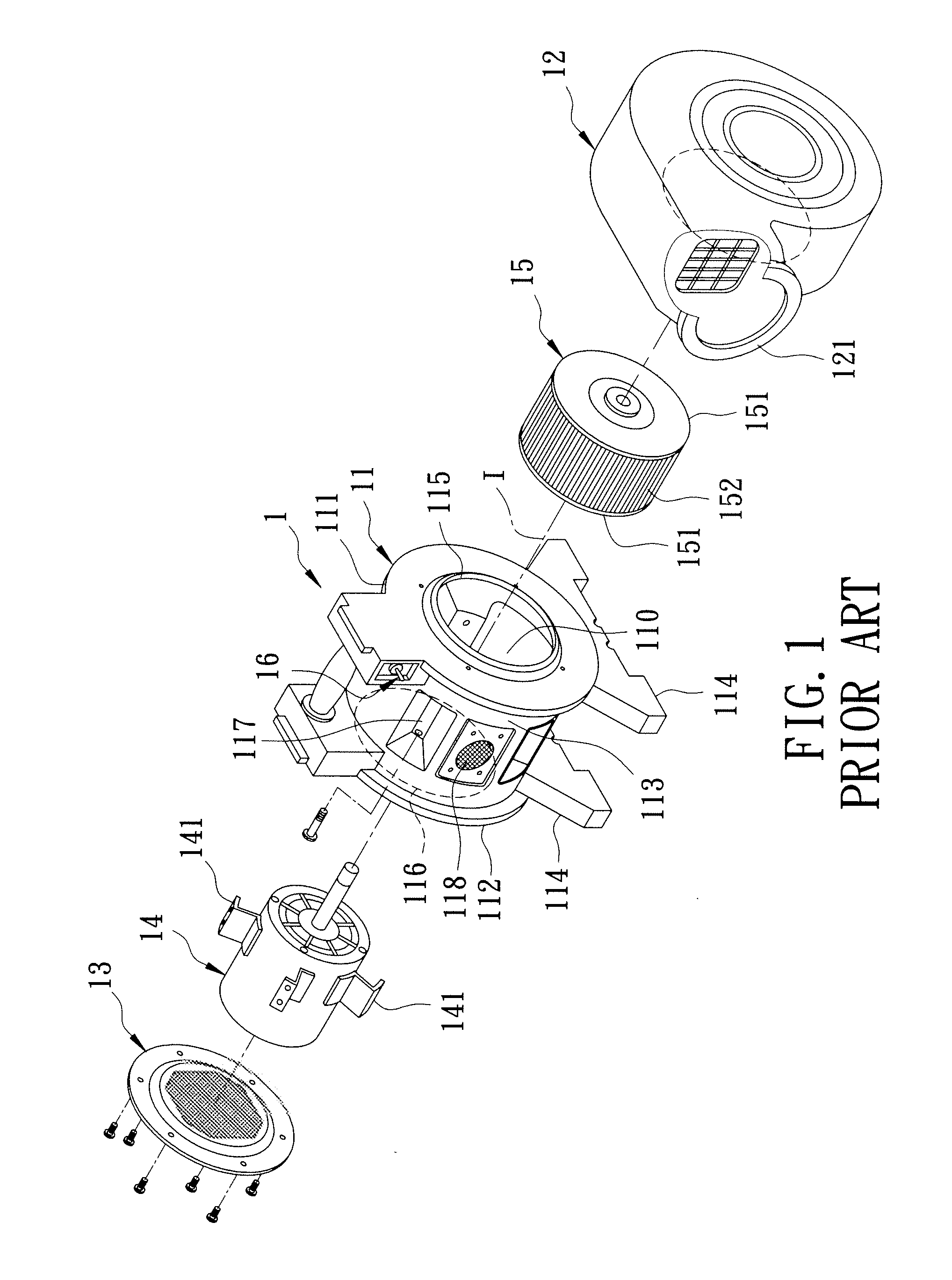
However, removal of the motor 14 cannot be performed unless the fan housing 12, the fan blade unit 15, and the screen plate 13 are removed from the motor housing 11, thereby resulting in difficulties in maintenance and repair of the blower 1.(2) When the motor 14 is operated, heat generates thereby.
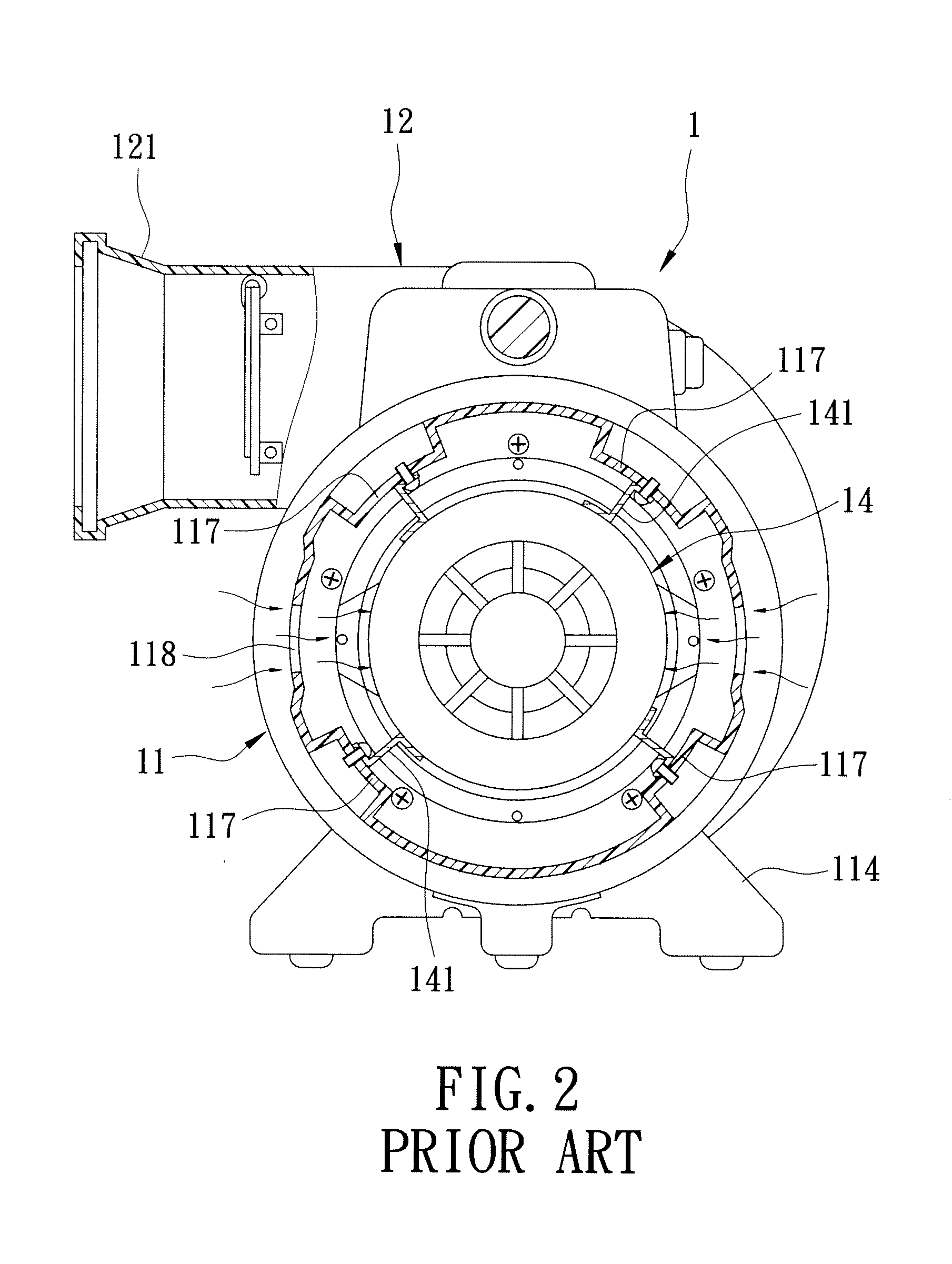
After a long period of use, such stress concentration results in deformation of the motor housing 11.

Method used


Image

  • Blower
  • Blower
  • Blower

Examples


Embodiment Construction

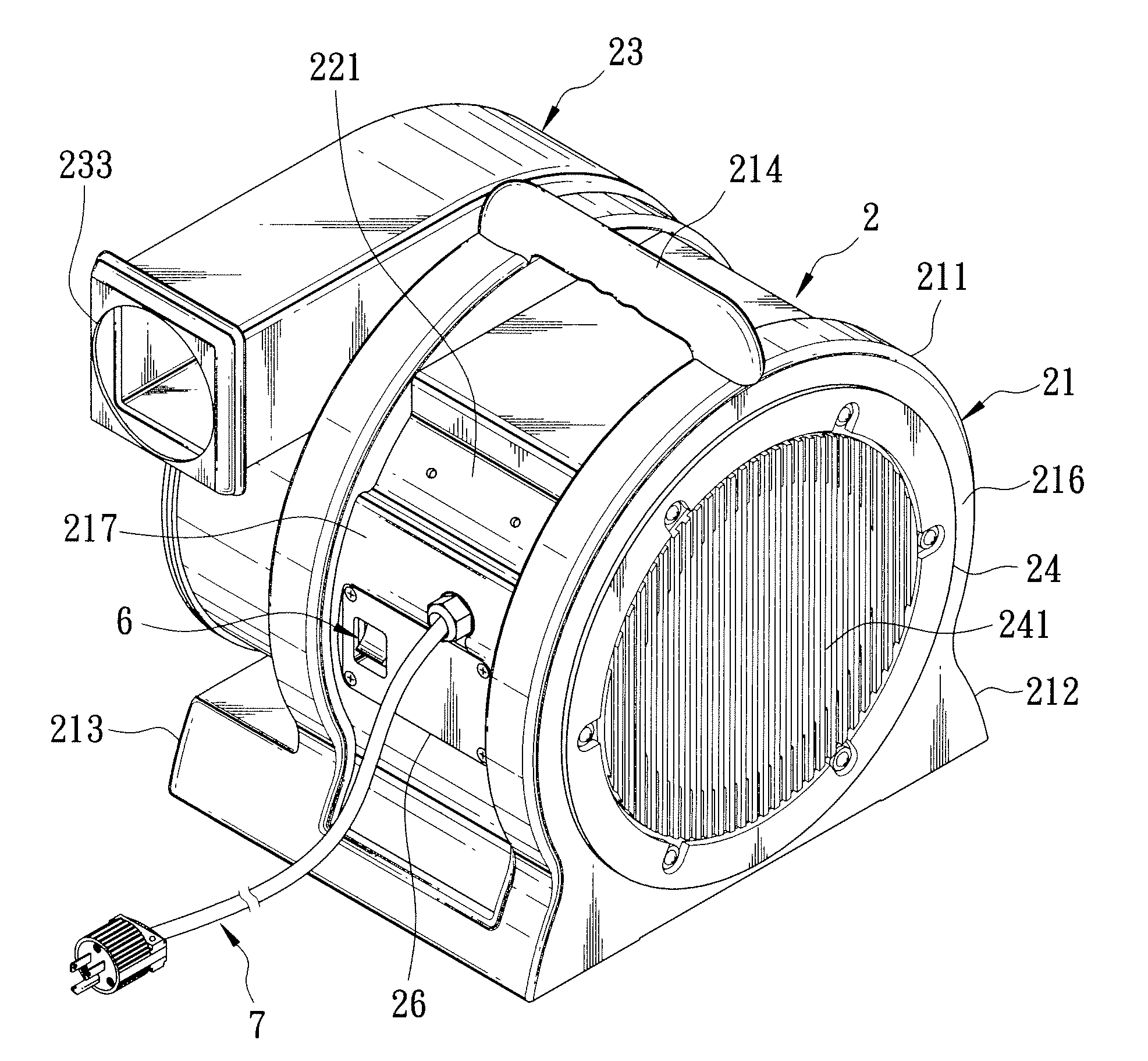
[0026]Referring to FIGS. 3, 4, and 6, the preferred embodiment of a blower according to this invention includes a housing unit 2, a fan blade unit 3 disposed in the housing unit 2, a driving device 4 for rotating the fan blade unit 3, a start capacitor 5 connected electrically to the driving device 5, a switch device 6 connected electrically to the driving device 5, and a power source device 7 connected electrically to the switch device 6.

[0027]The housing unit 2 includes a driver housing 21, and a fan housing 23 connected to and aligned with the driver housing 21 along an axis (II). The driver housing 21 includes a first accommodating space 210 for receiving the driving device 4. The fan housing 23 includes a second accommodating space 230 that receives the fan blade unit 3 and that is in spatial communication with the first accommodating space 210. The housing unit 2 further includes first and second screen plates 24, 25 disposed respectively on the driver housing 21 and the fan h...


PUM


Abstract

A blower includes a housing unit, a fan blade unit, a driving device, a start capacitor, a switch device, and a power source device. The power source device is connected electrically to the switch device. The housing unit includes a driver housing for receiving the driving device, and a fan housing for receiving the fan blade unit. The driver housing includes a mounting recess. The housing unit further includes a cover plate for covering removably the mounting recess. The start capacitor and the switch device are disposed removably within the mounting recess, and are connected electrically to the driving device at the mounting recess.

Description

BACKGROUND OF THE INVENTION[0001]1. Field of the Invention[0002]This invention relates to a blower, and more particularly to a blower for inflating objects, such as inflatable toys and mattresses.[0003]2. Description of the Related Art[0004]Referring to FIGS. 1 and 2, a blower 1 disclosed in U.S. Pat. No. 6,899,516 includes a motor housing 11, a fan housing 12, a screen plate 13 spaced apart from the fan housing 12 and disposed on the motor housing 11, a motor 14 disposed within the motor housing 11, a fan blade unit 15 driven by the motor 14 and disposed within the fan housing 12, and a switch 16 disposed on the motor housing 11.[0005]The motor housing 11 is disposed around an axis (I), defines an accommodating space 110 for receiving the motor 14, and has opposite first and second end walls 111, 112, a peripheral wall 113 interconnecting the first and second end walls 111, 112, and two spaced-apart support legs 114 connected fixedly to and disposed under the peripheral wall 113. T...

Claims


Application Information

Patent Timeline
Patent Type & Authority Applications(United States)
IPC IPC(8): F04D29/40
CPCF04D25/084F04D25/06
Inventor LIN, JEN-WEI
Owner LIN JEN WEI
Learn More