
Device for securing a dental implant in bone tissue, a method for making a surgical template and a method of securing a dental implant in bone tissue

a dental implant and bone tissue technology, applied in dental surgery, osteosynthesis devices, medical science, etc., can solve the problem of no longer being able to place a dental implant in the jawbon

Active Publication Date: 2009-09-24
NOBEL BIOCARE SERVICES AG
View PDF17 Cites 85 Cited by
  • Summary
  • Abstract
  • Description
  • Claims
  • Application Information

AI Technical Summary

Benefits of technology

[0019]The method comprises providing a guide sleeve having a first end that is provided with an interlock portion that is fits the interlock portion of the tubular mounting guide. The guide sleeve has an internal thread. A holder is provided that has dimensions that fit the guide sleeve such that the holder may be inserted into the guide sleeve. The holder comprises a screw that has an external thread complementary in shape to the internal thread of the guide sleeve such that the screw may cooperate with the guide sleeve. The holder further has a first end provided with a limit stop designed to cooperate with the guide sleeve such that, maximally, the holder may be inserted a predetermined distance into the guide sleeve. A second end of the holder is arranged to releasably secure a dental implant which is later to be secured in the bone tissue of a patient. A replica is provided that corresponds to an end part of the zygoma dental implant to be secured in the bone tissue of the patient.
[0020]In such an embodiment, the method further comprises providing a connection piece which has one end adapted to be connected to the holder and one end adapted to receive the replica and hold the replica such that the replica forms an angle with the longitudinal axis of the holder. The holder is inserted into the guide sleeve and screwed into the guide sleeve. The connection piece is secured to the second end of the holder. The guide sleeve is inserted into the tubular mounting guide such that the interlock portion of the guide sleeve) engages the interlock portion of the tubular mounting guide. The guide sleeve is then rotated together with the holder and the connection piece until the connection piece is in a position where a fastening member can be inserted through the second hole and brought against the connection piece. The replica is then brought against...

Problems solved by technology

There are some patients that have suffered regress of the jawbone to such an extent that it is no longer possible to place a dental implant in the jawbone.

Method used


Image

  • Device for securing a dental implant in bone tissue, a method for making a surgical template and a method of securing a dental implant in bone tissue
  • Device for securing a dental implant in bone tissue, a method for making a surgical template and a method of securing a dental implant in bone tissue
  • Device for securing a dental implant in bone tissue, a method for making a surgical template and a method of securing a dental implant in bone tissue

Examples


Embodiment Construction

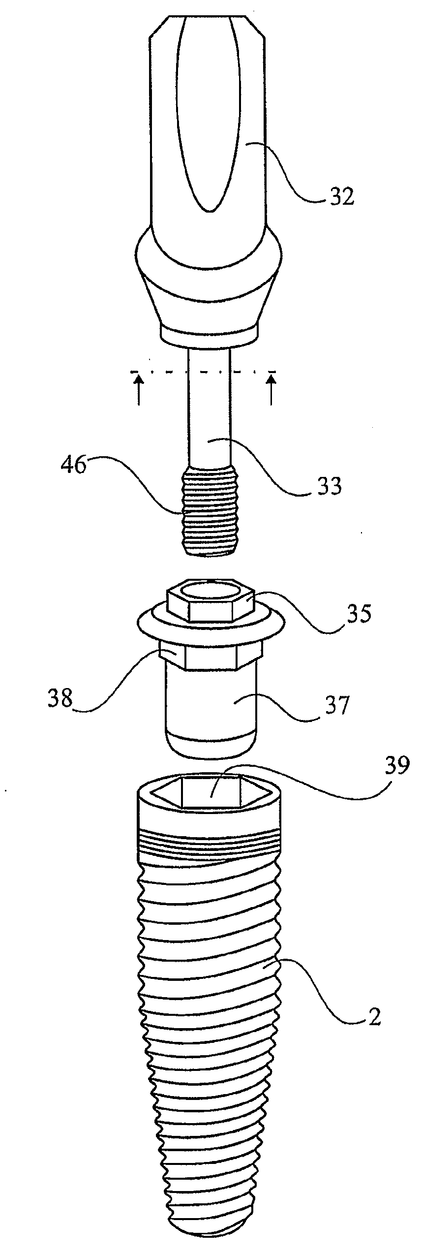
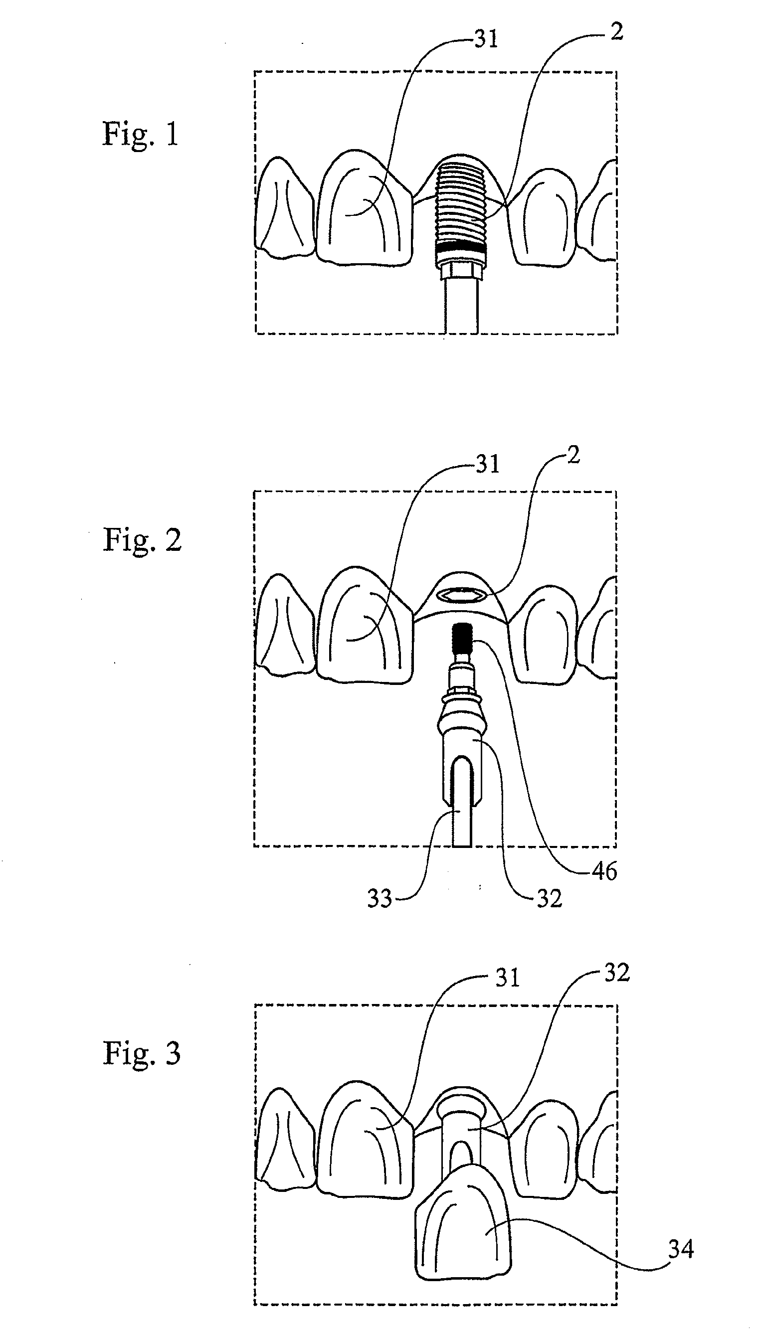
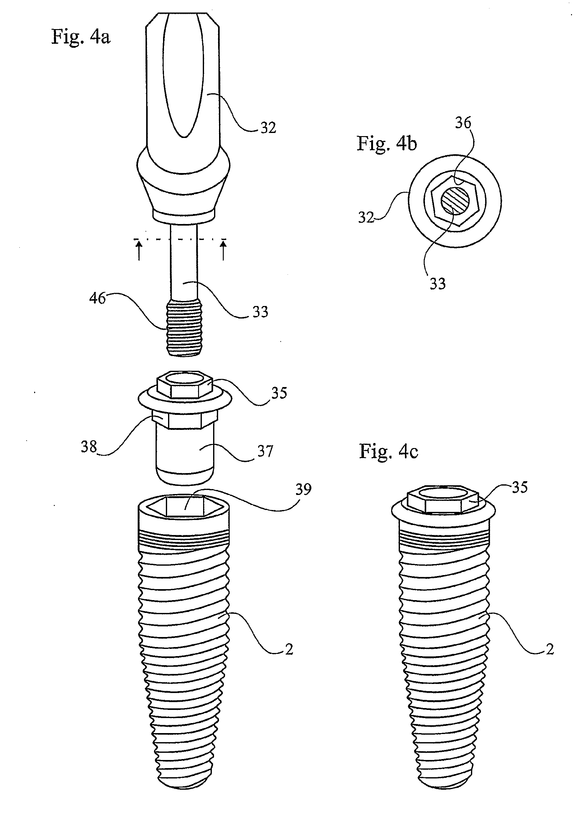
[0068]As a further explanation of the background, a sequence for giving a patient a dental prosthesis is illustrated in FIGS. 1-3. With reference to FIG. 1, it can be seen how a dental implant is screwed into the jawbone of the patient. Although not illustrated, it should be understood that a hole for the dental implant 2 has previously been drilled in the patient's jawbone. As showed in FIG. 2, an abutment 32 can then be secured to the dental implant 2. The abutment 32 may be fastened to the implant 2 by means of a screw 33. When the abutment 32 has been fastened to the dental implant 2, a dental prosthesis 34 can be cemented to the abutment 32 as indicated in FIG. 3. In order for the prosthesis 34 to be correctly oriented, the abutment 32 also needs to be correctly oriented. The reference numeral 31 refers to the natural teeth of the patient but could also be understood as representing already installed prostheses.

[0069]The fastening of the abutment 32 to the dental implant 2 is i...


PUM


Abstract

The application relates to a device and a method for securing a dental implant in the bone tissue of a patient. The device can comprise a guide sleeve and a holder. The guide sleeve can have an interlock portion and a central bore having an internal thread. The holder can hold the dental implant and be configured to be inserted into the central bore of the guide sleeve. The holder can comprise an external thread that is configured to engage the internal thread of the guide sleeve such that the holder may threadingly engage the guide sleeve. The holder can further comprise a limit stop that can be configured to contact the guide sleeve for limiting the longitudinal position of the holder relative to the guide sleeve. The holder can releasably retain the dental implant and faciltate implantion of the implant into the bone tissue of the patient.

Description

CROSS-REFERENCE TO RELATED APPLICATIONS[0001]This application is a national stage application under 35 U.S.C. § 371 of PCT Application No. PCT / SE2007 / 000431 designating the United States, filed on May 4, 2007. The PCT Application was published in English as WO 2007 / 129955 A1 on Nov. 15, 2007 and claims the benefit of the earlier filing date of Swedish Patent Application Nos. 0600978-1, filed May 4, 2006, and 0600979-9, filed May 4, 2006. The contents of PCT Application No. PCT / SE2007 / 000431, including publication WO 2007 / 129955 A1, and Swedish Patent Application Nos. 0600978-1, filed May 4, 2006, and 0600979-9, filed May 4, 2006 are incorporated herein by reference in their entirety.BACKGROUND[0002]1. Field of the Inventions[0003]The present application relates to a device for securing a dental implant in bone tissue, for example the jawbone of a patient or the zygomatic bone of a patient. The application also relates to a method of making a surgical template and to a method of secu...

Claims


Application Information

Patent Timeline
IPC IPC(8): A61C8/00
CPCA61C1/084A61C8/009A61C8/0089A61C8/0034A61C1/085A61B17/86A61C8/00
Inventor BRAJNOVIC, IZIDOR
Owner NOBEL BIOCARE SERVICES AG
Learn More