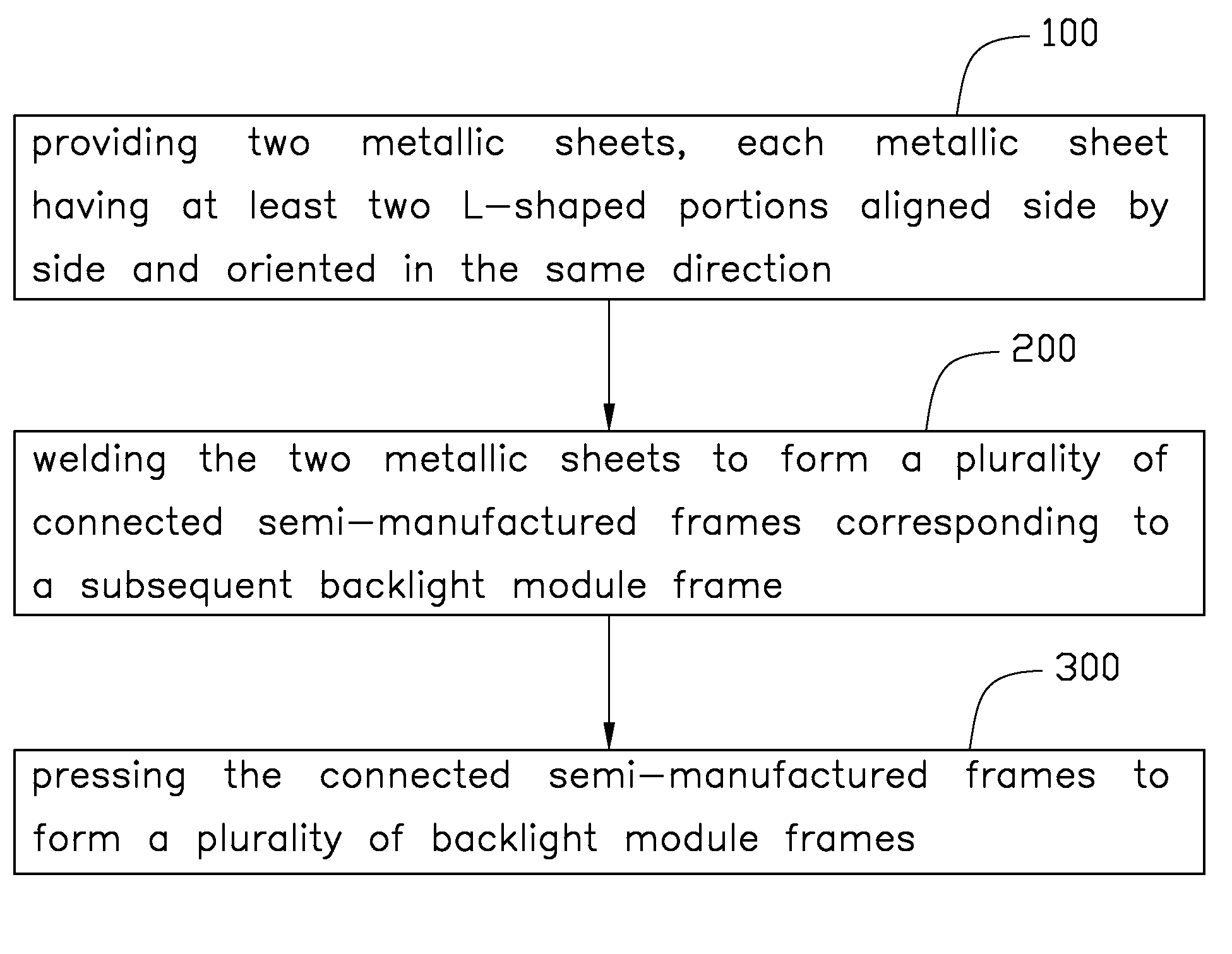
Method for making backlight module frame
- Summary
- Abstract
- Description
- Claims
- Application Information
AI Technical Summary
Problems solved by technology
Method used
Image

Examples
Example
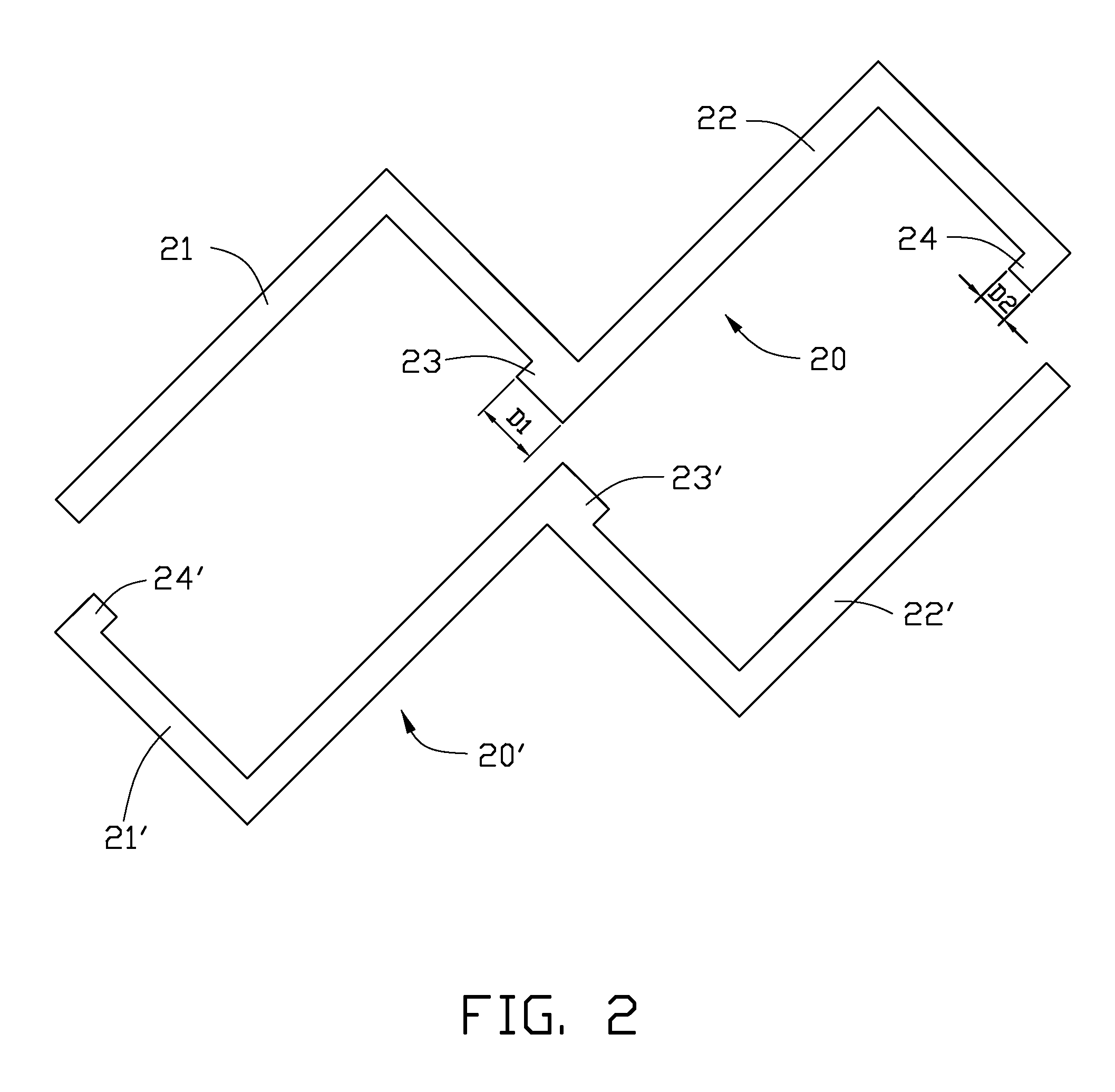
[0024]In the first embodiment, forming two backlight module frames only needs three welding processes, one less welding process is performed than a conventional method described in background, and thus, requiring less welding time. In addition, it is convenient for the backlight module frames to be mass-produced.
[0025]Referring to FIGS. 4 and 5 together, a method for making backlight module frame in accordance with a second exemplary embodiment, includes performing the following:
[0026]Providing two metallic sheets 30, 30′, each metallic sheet having four L-shaped portions, i.e., the metallic sheets 30 having a first L-shaped portion 31, a second L-shaped portion 32, a third L-shaped portion 33 and a fourth L-shaped portion 34 aligned side by side; and the metallic sheets 30′ having a first L-shaped portion 31′, a second L-shaped portion 32′, a third L-shaped portion 33′ and a fourth L-shaped portion 34′ aligned side by side;
[0027]Welding the two metallic sheets 30, 30′ to form four ...
PUM
| Property | Measurement | Unit |
|---|---|---|
| Width | aaaaa | aaaaa |
| Metallic bond | aaaaa | aaaaa |
Abstract
Description
Claims
Application Information
 - R&D Engineer
- R&D Manager
- IP Professional
- Industry Leading Data Capabilities
- Powerful AI technology
- Patent DNA Extraction
Browse by: Latest US Patents, China's latest patents, Technical Efficacy Thesaurus, Application Domain, Technology Topic.
© 2024 PatSnap. All rights reserved.Legal|Privacy policy|Modern Slavery Act Transparency Statement|Sitemap