
Method for controlling flow of eggs in a uterine tube

Active Publication Date: 2009-09-24
FORSELL PETER
View PDF14 Cites 49 Cited by
  • Summary
  • Abstract
  • Description
  • Claims
  • Application Information

AI Technical Summary

Benefits of technology

[0014]The present invention provides an advantageous combination of the method steps (a) and (b), which results in a two-stage influence on the flow of eggs in the uterine tube. Thus, applying a relatively weak force against the uterine tube wall portion gently constricts the uterine tube wall and the constricted wall portion is stimulated to achieve the desired final influence on the flow of eggs in the uterine tube. The phrase “gently constricts a portion of the uterine tube wall” is to be understood as constricting the uterine tube wall portion without substantially hampering the blood circulation in the uterine tube wall.
[0121]The method of the invention may comprise implanting in the patient an internal source of energy, and supplying energy from the internal source of energy for the operation of the constriction / stimulation unit. The method may further comprise implanting in the patient a switch operable to switch from an “off” mode, in which the internal source of energy is not in use, to an “on” mode, in which the internal source of energy supplies energy for the operation of the constriction / stimulation unit, and / or for energizing implanted electronic components of the constriction / stimulation unit. The switch may be operated by the energy of the first form or by the energy of the second form. The described switch arrangement reduces power consumption of the constriction / stimulation unit between operations.

Problems solved by technology

Many women have difficulties getting pregnant.
However, this method is not always easy and safe and is furthermore very expensive, particularly when repeated, which often is the case.
Contraceptive drugs may cause blood clots and other serious complications.

Method used


Image

  • Method for controlling flow of eggs in a uterine tube
  • Method for controlling flow of eggs in a uterine tube
  • Method for controlling flow of eggs in a uterine tube

Examples


Embodiment Construction

[0272]Referring to the drawing figures, like reference numerals designate identical or corresponding elements throughout the several figures.

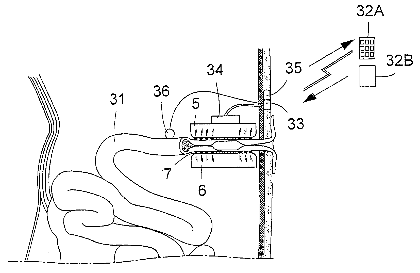
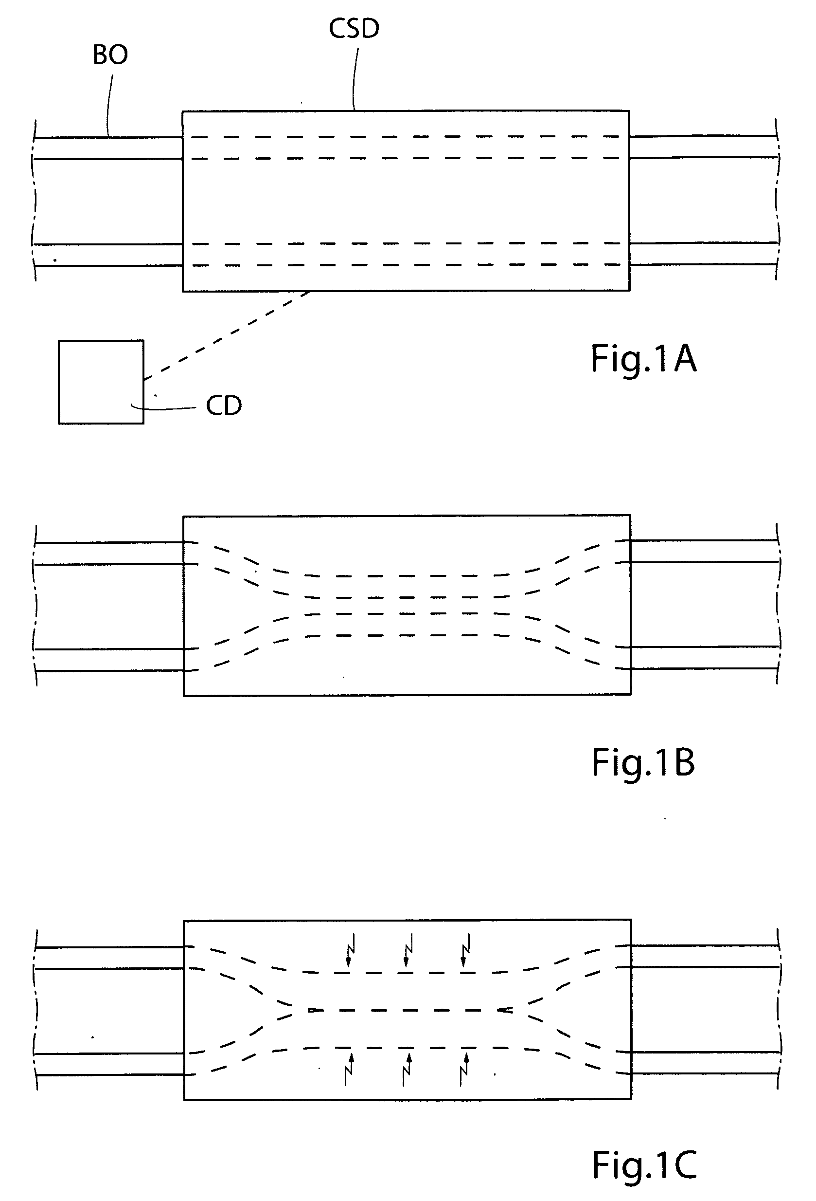
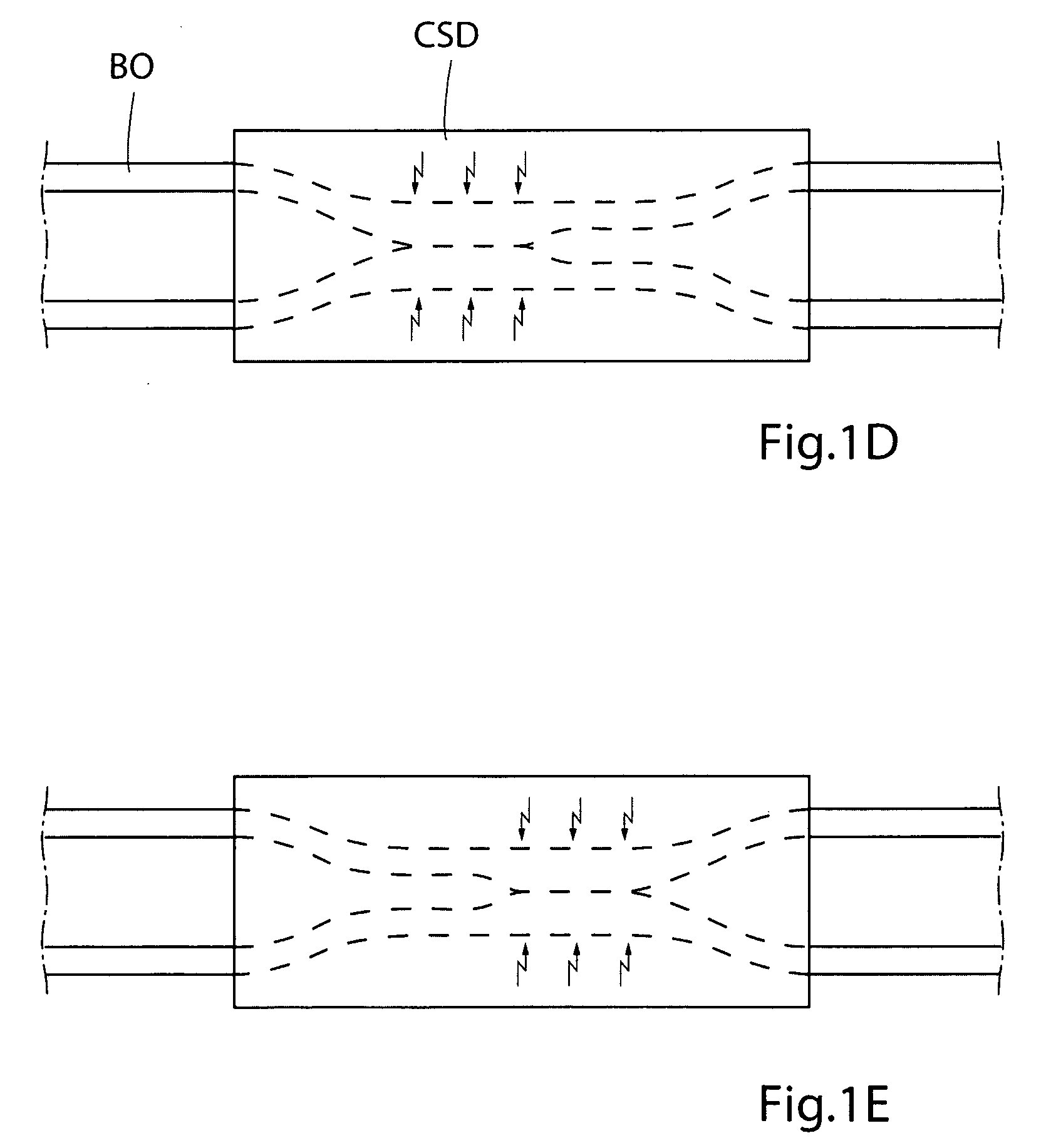
[0273]FIGS. 1A, 1B and 1C schematically illustrate different states of operation of a generally designed apparatus used for practicing the method of the present invention, when the apparatus is applied on a wall portion of a bodily organ designated BO, the bodily organ being a uterine tube of a female patient. The apparatus includes a constriction device and a stimulation device, which are designated CSD, and a control device designated CD for controlling the constriction and stimulation devices CSD. FIG. 1A shows the apparatus in an inactivation state, in which the constriction device does not constrict the uterine tube BO and the stimulation device does not stimulate the uterine tube BO. FIG. 1B shows the apparatus in a constriction state, in which the control device CD controls the constriction device to gently constrict the uterine tube wal...


PUM


Abstract

There is provided a method for controlling a flow of eggs in a uterine tube formed by a uterine tube wall of a patient. The method comprises gently constricting (i.e., without substantially hampering the blood circulation in the uterine tube wall) at least one portion of the uterine tube wall to influence the flow of eggs in the uterine tube, and stimulating the constricted wall portion to cause contraction of the uterine tube wall portion to further influence the flow of eggs in the uterine tube. The method can be used for restricting or stopping the flow of eggs in the uterine tube, or for actively moving the fluid in the uterine tube, with a low risk of injuring the uterine tube.

Description

CROSS-REFERENCE TO RELATED APPLICATION[0001]This application claims the benefit of Provisional Application No. 60 / 960,716, filed Oct. 11, 2007, the entire contents of which are hereby incorporated by reference in this application.FIELD OF THE INVENTION[0002]The present invention relates to controlling the flow of eggs in bodily organs, and in particular, to an apparatus for controlling the flow of eggs in the uterine tubes of a female patient.BACKGROUND OF THE INVENTION[0003]The invention adapted to affect the transportation of egg in the uterine tube may help women to avoid pregnancy by preventing the egg to reach the sperm or even to make it easier to get pregnant by withholding the egg in the best part of the uterine tube for up to 12 hours or affect the flow of the sperm. Many women have difficulties getting pregnant. Old age when trying to get pregnant with lower fertility rate is one main reason.[0004]Artificial insemination is one way to promote pregnancy and this way has inc...

Claims


Application Information

Patent Timeline
IPC IPC(8): A61N1/36A61F6/20
CPCA61M1/1068A61N1/3605A61N1/36514A61M1/122A61N1/36578A61N1/403A61N1/36564A61F6/20A61M60/148A61F6/206
Inventor FORSELL, PETER
Owner FORSELL PETER
Learn More