Eureka AIR delivers breakthrough ideas for toughest innovation challenges, trusted by R&D personnel around the world.

Implantable Medical Lead Circuitry and Methods for Reducing Heating and/or Induced Current

Active Publication Date: 2010-08-26
PACESETTER INC
View PDF5 Cites 14 Cited by
  • Summary
  • Abstract
  • Description
  • Claims
  • Application Information

AI Technical Summary

Benefits of technology

[0005]Disclosed herein is an implantable medical lead for coupling to an implantable pulse generator and configured for improved MRI safety. In particular, embodiments of leads disclosed herein may improve MRI safety by reducing induced currents in medical leads. Such reduction may reduce or even eliminate risks of stimulation and / or heating resulting from exposure of medical leads to magnetic and / or electrical fields.
[0007]Disclosed herein is a method of using an implantable medical lead for improved MRI safety. In particular, embodiments of methods disclosed herein may improve MRI safety by reducing induced currents in medical leads. Such reduction may reduce or even eliminate risks of stimulation and / or heating resulting from exposure of medical leads to magnetic and / or electrical fields.

Problems solved by technology

Existing implantable medical leads for use with implantable pulse generators, such as neurostimulator, pacemakers, defibrillators or implantable cardioverter defibrillators (“ICD”), are prone to heating and induced current when placed in the strong magnetic (static, gradient and RF) fields of a magnetic resonance imaging (“MRI”) machine.
Heating and induced current in the lead may result in deterioration of stimulation thresholds or, in the context of a cardiac lead, even increase the risk of cardiac tissue damage and perforation.
Moreover, induced currents may cause erroneous pacing or even fibrillation.
The diagnosis and treatment options enhanced by MRI are only going to grow over time.

Method used


Image

  • Implantable Medical Lead Circuitry and Methods for Reducing Heating and/or Induced Current
  • Implantable Medical Lead Circuitry and Methods for Reducing Heating and/or Induced Current
  • Implantable Medical Lead Circuitry and Methods for Reducing Heating and/or Induced Current

Examples


Embodiment Construction

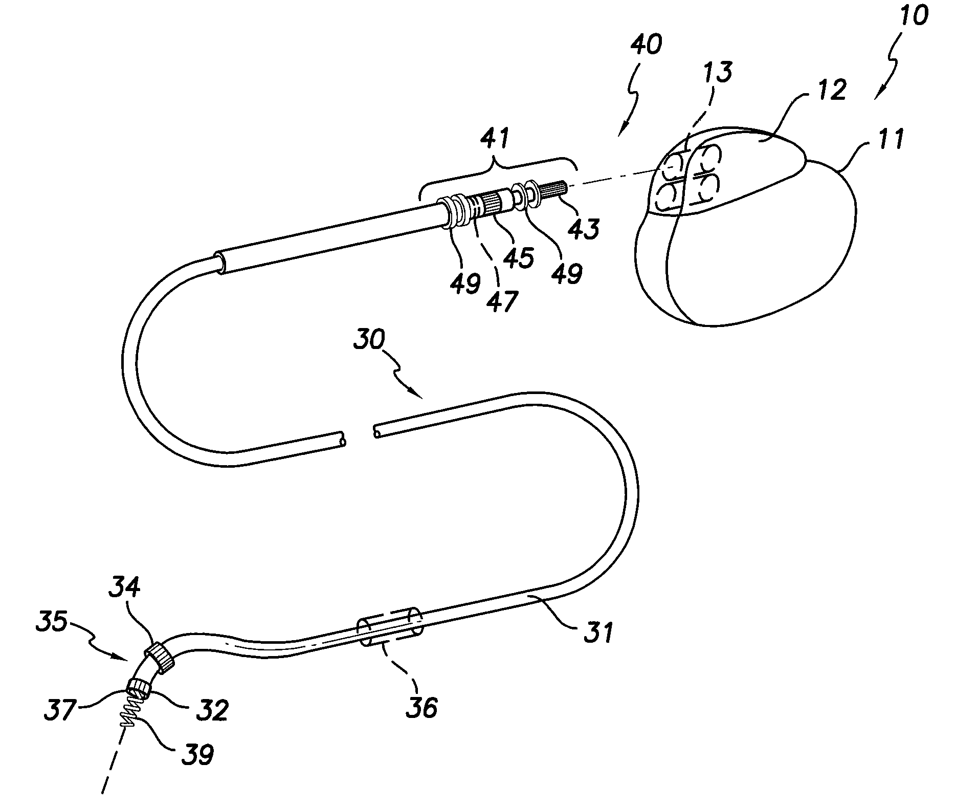
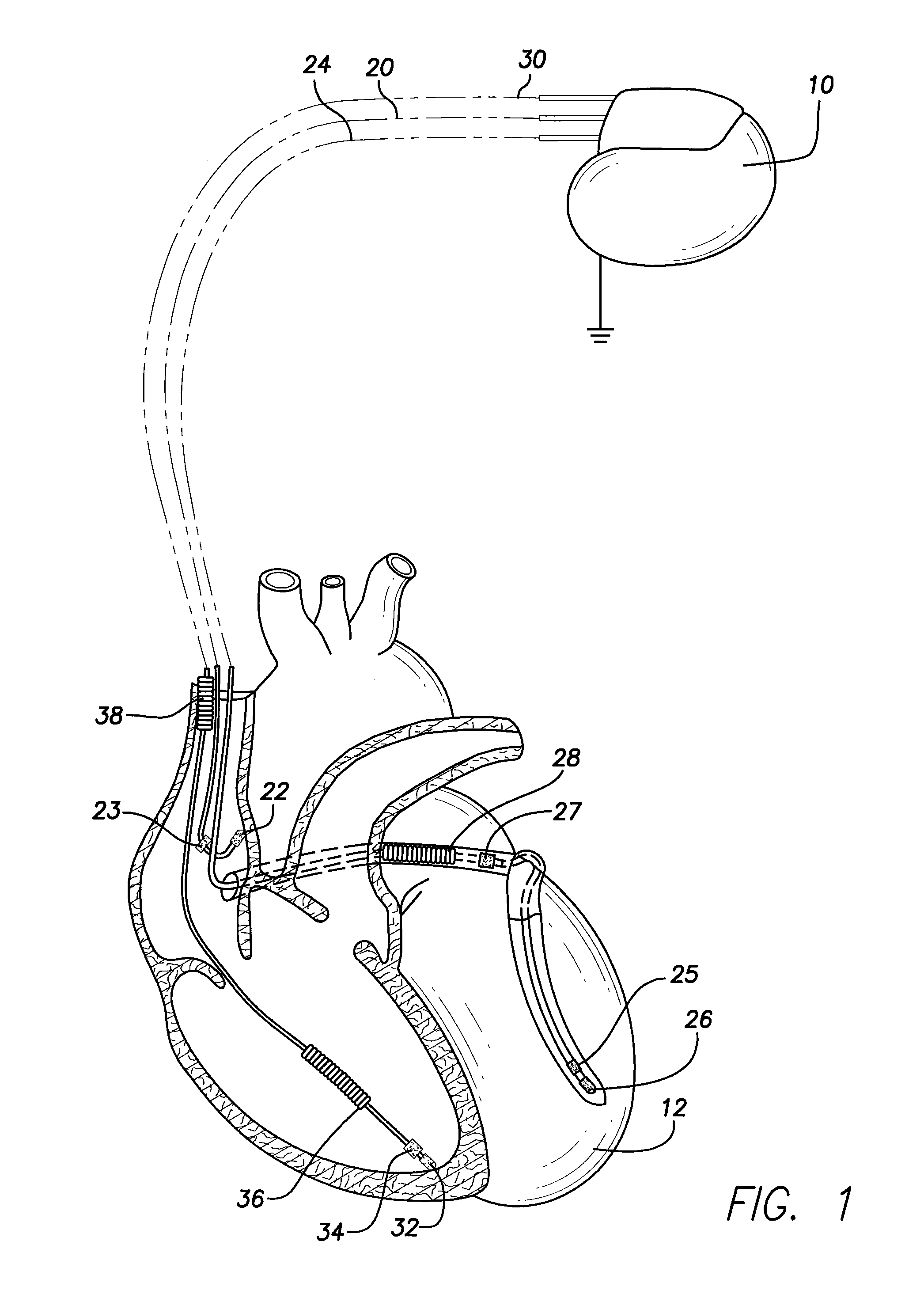
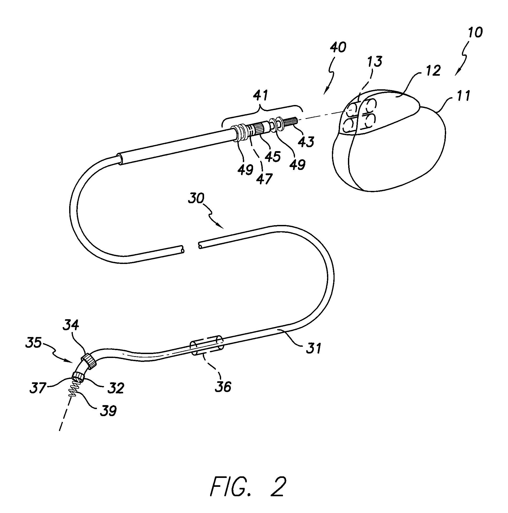
[0017]The following description is of embodiments presently contemplated for practicing various aspects of the invention. This description is not to be taken in a limiting sense, but is made merely for the purpose of describing general principles. The scope of the invention should be ascertained with reference to the issued claims. In the description that follows, like numerals or reference designators will be used to refer to like parts or elements throughout.

[0018]Embodiments are described herein in relation to a cardiac stimulation device capable of delivering precisely ordered stimulation pulses to multiple chambers of the heart, referred to herein as multi-chamber stimulation, or to multiple sites within a chamber of the heart, referred to herein as multi-site stimulation. The stimulation device is intended for use in patients suffering from hemodynamic dysfunction, which may or may not be accompanied by conduction disorders. Precisely controlled stimulation at multiple sites o...


PUM


Abstract

An implantable medical lead for coupling to an implantable pulse generator may be configured for improved safety. The lead may include: a first electrode; a second electrode in electrical communication with the first electrode; and an active circuit element in electrical communication with the first electrode and the second electrode. The active circuit element may be configured to change an impedance of the lead. The active circuit element may be configured to change the impedance of the lead in response to a pacing signal or a signal having opposite polarity to a pacing signal. A method of using an implantable medical lead for improved safety may include changing an impedance of an implantable medical lead from a relatively high impedance to a relatively low impedance and / or changing an impedance of an implantable medical lead from a relatively low impedance to a relatively high impedance.

Description

FIELD OF THE INVENTION[0001]The present invention relates to medical methods and apparatus. More specifically, the present invention relates to implantable medical leads and methods of utilizing such leads.BACKGROUND OF THE INVENTION[0002]Existing implantable medical leads for use with implantable pulse generators, such as neurostimulator, pacemakers, defibrillators or implantable cardioverter defibrillators (“ICD”), are prone to heating and induced current when placed in the strong magnetic (static, gradient and RF) fields of a magnetic resonance imaging (“MRI”) machine. The heating and induced current are the result of the lead acting like an antenna in the magnetic fields generated during an MRI. Heating and induced current in the lead may result in deterioration of stimulation thresholds or, in the context of a cardiac lead, even increase the risk of cardiac tissue damage and perforation. Moreover, induced currents may cause erroneous pacing or even fibrillation.[0003]Over fifty...

Claims


Application Information

Patent Timeline
IPC IPC(8): A61N1/05
CPCA61N1/3718A61N1/37
Inventor MOULDER, J. CHRISTOPHERCHOLETTE, MARTIN
Owner PACESETTER INC
Why Eureka
Eureka Blog
Learn More