Eureka AIR delivers breakthrough ideas for toughest innovation challenges, trusted by R&D personnel around the world.

Coupled pivoted acceleration sensors

Active Publication Date: 2009-10-01
PCB PIEZOTRONICS OF NORTH CAROLINA
View PDF21 Cites 2 Cited by
  • Summary
  • Abstract
  • Description
  • Claims
  • Application Information

AI Technical Summary

Benefits of technology

[0007]Accordingly, an object of the present invent

Problems solved by technology

Though the freed strain gauge was an improvement over previous strain gauges, it is still not the optimal structure to detect strain.
The manufacturing process also imposes an upper limit on the resistivity in the freed gauge, which limits the gauge factor and thus, the sensitivity of the gauge.
In addition, heat dissipation limits the length of a device, such that the gauges must be stitched back and forth across a gap over a hinge until there is enough total length to give the needed resistance.

Method used


Image

  • Coupled pivoted acceleration sensors
  • Coupled pivoted acceleration sensors
  • Coupled pivoted acceleration sensors

Examples


Embodiment Construction

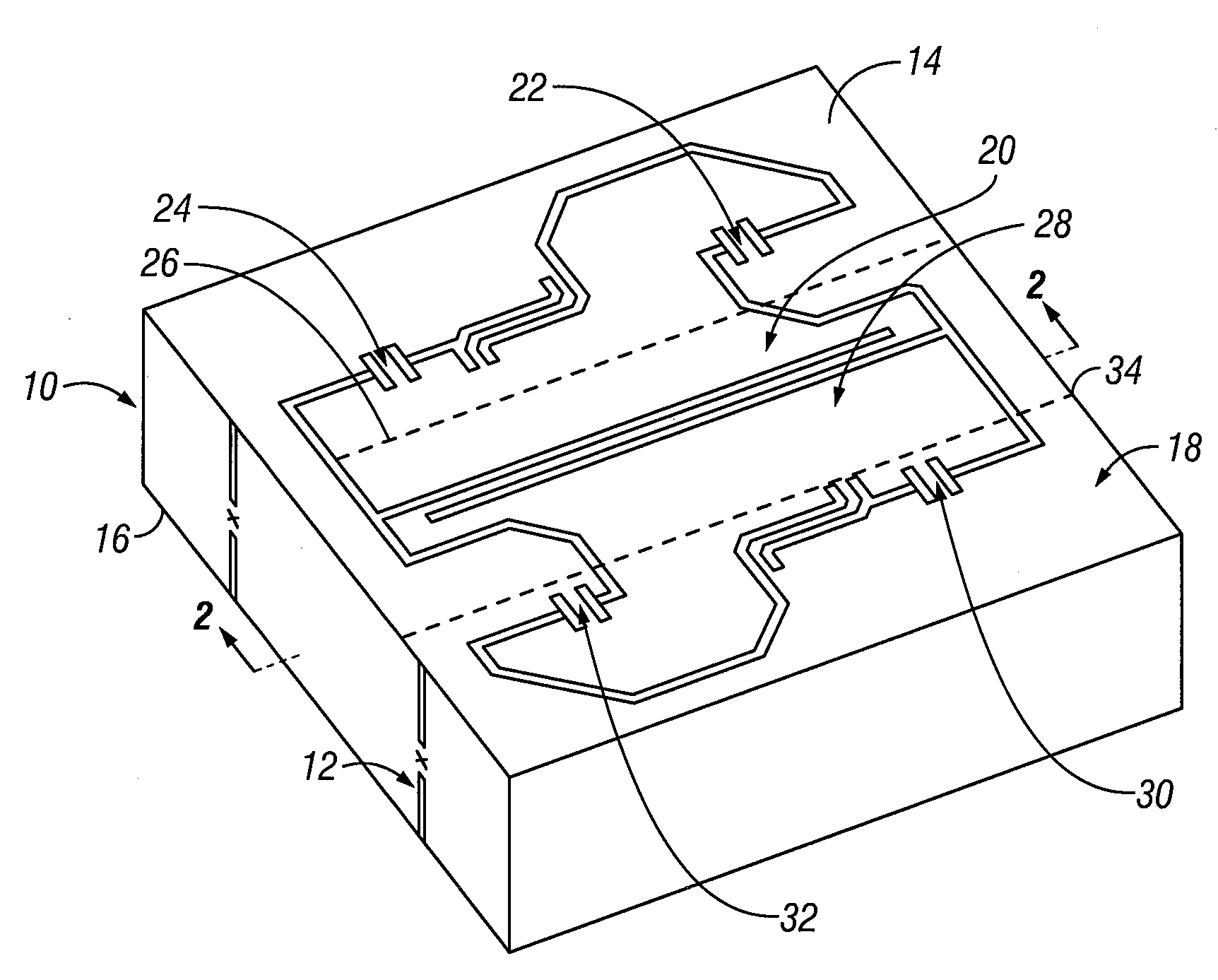
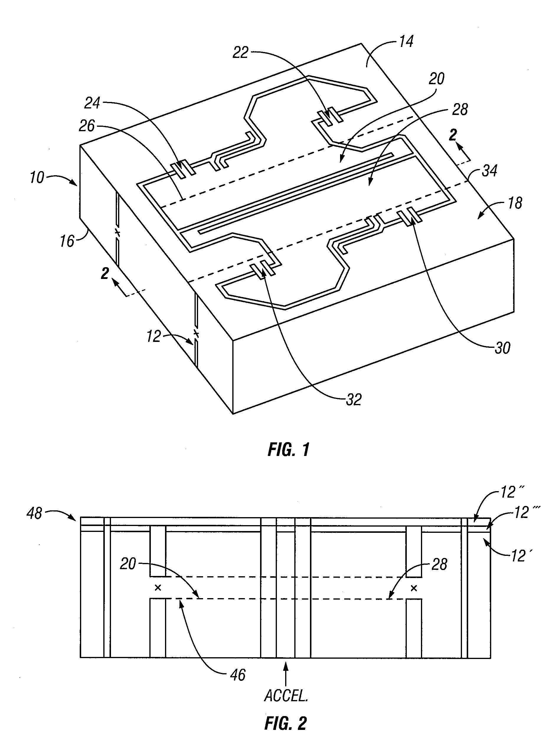
[0016]In one embodiment of the present invention, an apparatus and methods are provided for generating a signal in response to a translational acceleration. The signal is cancelled in response to a rotational acceleration. A full-bridge accelerometer is coupled on a fixed reference frame without crossovers.

[0017]In one embodiment of the present invention, as set forth in FIG. 1, an apparatus 10 is a coupled pivoted acceleration sensor with a substrate 12 that is substantially parallel to first and second surfaces 14 and 16. A reference frame 18 is provided. A first unbalanced seismic mass 20 is suspended within the reference frame. 18 and is coupled with the reference frame 18 through first and second strain gauges 22 and 24. The first and second strain gauges 22 and 24 are located along a pivot axis 26 of the first unbalanced seismic mass 20. The first and second strain gauges 22 and 24 are first and second piezoresistors on the first surface 14 of the substrate 12. In the FIG. 1 e...


PUM


Abstract

A pivoted acceleration sensor has a substrate that is substantially parallel to first and second surfaces. A reference frame is provided. A first unbalanced seismic mass is suspended within the reference frame and is coupled with the reference frame through first and second strain gauges. The first and second strain gauges are located along a pivot axis of the first unbalanced seismic mass. The first and second strain gauges are first and second piezoresistors on the first surface of the substrate, A second unbalanced seismic mass is flexibly coupled with the first unbalanced seismic mass. The second unbalanced seismic mass is suspended within the reference frame and is coupled with the reference frame through third and fourth strain gauges. The third and fourth strain gauges are located along a pivot axis of the second unbalanced seismic mass. The third and fourth strain gauges are third and fourth piezoresistors on the first surface of the substrate. Metallization on the first surface of the substrate is configured to connect the first, second, third and fourth piezoresistors in a bridge configuration without crossovers.

Description

BACKGROUND OF THE INVENTION[0001]1. Field of the Invention[0002]This invention relates generally to acceleration sensors, and more particularly to pivoted acceleration sensor coupled on a fixed reference frame without crossovers.[0003]2. Description of the Related Art[0004]In pressure and acceleration sensors, it is desired to produce a relatively large signal power from a relatively small amount of energy absorbed from the medium. The goal is to minimize the mechanical energy necessary to produce a desired output signal. In pressure sensors, energy is absorbed from the medium as pressure deflects a diaphragm. Generally, a bar deeply notched at the center and its ends is placed across a diaphragm. Gauges are placed on the plane surface opposite the notched bottoms. The strain of the bending bar is concentrated at the bottom of the notches. In acceleration sensors, energy is absorbed from the acceleration field as the seismic mass deflects relative to its reference frame. For example...

Claims


Application Information

Patent Timeline
IPC IPC(8): G01P15/12
CPCG01P15/123G01P15/0888
Inventor WILNER, LESLIE BRUCE
Owner PCB PIEZOTRONICS OF NORTH CAROLINA
Why Eureka
Eureka Blog
Learn More