System and method for reducing rotor loads in a wind turbine upon detection of blade-pitch failure and loss of counter-torque

a technology of rotor load and wind turbine, which is applied in the direction of electric generator control, machines/engines, mechanical equipment, etc., can solve the problems of one blade pitching towards feather, high rotor speed, and high load in many components of the wind turbin

Active Publication Date: 2009-10-01
GENERAL ELECTRIC CO
View PDF43 Cites 48 Cited by
  • Summary
  • Abstract
  • Description
  • Claims
  • Application Information

AI Technical Summary

Problems solved by technology

One of the most severe situations for a wind turbine is a combination of the loss of counter-torque provided by the generator, for example, loss of grid connection, and the failure of one of the blades to pitch towards feather.
The pitch failure causes blade asymmetry and the loss of counter-torque causes high rotor speed.
The combination of these two conditions causes a large aerodynamic imbalance in the rotor that may cause very high loads in many components in the wind turbine, particularly in the tower top (e.g., hub, main bearing, main frame, and the like).

Method used


Image

  • System and method for reducing rotor loads in a wind turbine upon detection of blade-pitch failure and loss of counter-torque
  • System and method for reducing rotor loads in a wind turbine upon detection of blade-pitch failure and loss of counter-torque
  • System and method for reducing rotor loads in a wind turbine upon detection of blade-pitch failure and loss of counter-torque

Examples


Embodiment Construction

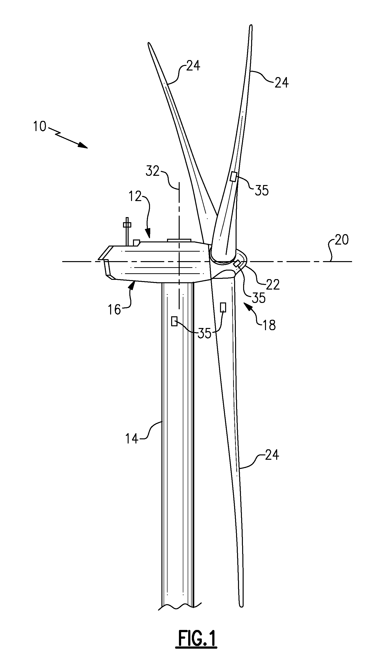
[0025]As used herein, the term “blade” is intended to be representative of any device that provides reactive force when in motion relative to a surrounding fluid. As used herein, the term “wind turbine” is intended to be representative of any device that generates rotational energy from wind energy, and more specifically, converts kinetic energy of wind into mechanical energy. As used herein, the term “wind generator” is intended to be representative of any wind turbine that generates electrical power from rotational energy generated from wind energy, and more specifically, converts mechanical energy converted from kinetic energy of wind to electrical power. As used herein, the term “windmill” is intended to be representative of any wind turbine that uses rotational energy generated from wind energy, and more specifically mechanical energy converted from kinetic energy of wind, for a predetermined purpose other than generating electrical power, such as, but not limited to, pumping a...


PUM


Abstract

A system and method for reducing rotor loads in a wind turbine that includes a brake and one or more rotor blades coupled to a rotor. Upon detection of a loss of counter torque and a blade-pitch failure in at least one rotor blade, a processor reduces a generator overspeed threshold value by a predetermined amount and determines a brake-release threshold value. The brake is applied to slow the rotor if the generator / rotor speed exceeds the reduced generator / rotor overspeed threshold value. In addition, the brake is applied to slow the rotor until the generator / rotor speed is below the brake-release threshold value. The rate of change of the pitch angle of the rotor blade may be varied as the blade moves toward feather in response to the detected blade-pitch failure.

Description

BACKGROUND[0001]This invention relates generally to wind turbines, and more particularly to methods and apparatus for efficiently reducing rotor loads in a wind turbine upon detection of a blade-pitch failure and loss of counter-torque, for example, a grid anomaly.[0002]Recently, wind turbines have received increased attention as an environmentally safe and relatively inexpensive alternative energy source. With this growing interest, considerable efforts have been made to develop wind turbines that are reliable and efficient.[0003]Generally, a wind turbine includes a rotor having multiple blades. The rotor is mounted within a housing or nacelle, which is positioned on top of a truss or tubular tower. Utility grade wind turbines (i.e., wind turbines designed to provide electrical power to a utility grid) can have large rotors (e.g., 80 or more meters in diameter). Blades on these rotors transform wind energy into a rotational torque or force that drives one or more generators, rotati...

Claims


Application Information

Patent Timeline
Patent Type & Authority Applications(United States)
IPC IPC(8): F03D9/00F03D7/00
CPCF03D7/0224F03D7/0228F03D7/0244F03D7/0264Y02E10/723F05B2260/80F05B2270/1011F05B2270/107F05B2270/337F03D7/043Y02E10/72Y02P80/10
Inventor KAMMER, LEONARDO CESARBRAICKS, AXELOING, HUBERT
Owner GENERAL ELECTRIC CO
Why Eureka
Try Eureka