Ink jet printing apparatus and print head recovery method

Inactive Publication Date: 2009-10-01
CANON KK
View PDF12 Cites 14 Cited by
  • Summary
  • Abstract
  • Description
  • Claims
  • Application Information

AI Technical Summary

Benefits of technology

[0010]The present invention provides an ink jet printing apparatus and a print head recovery method that effectively perform preliminary ejections by

Problems solved by technology

Ink bubbles, when formed in the nozzle openings of the print head in particular, may cause ink ejection anomalies, such as ink ejection failures, a deflection of ink ejecting direction and reduced ink ejection volumes.
However, the suction operation to suck out bubbles from the nozzle openings of the print head as described above requires a suction mechanism such as a negative pressure pump, leading to increased complexity and cost of the apparatus as a whole.

Method used


Image

  • Ink jet printing apparatus and print head recovery method
  • Ink jet printing apparatus and print head recovery method
  • Ink jet printing apparatus and print head recovery method

Examples


first embodiment

[0043]FIG. 1 to FIG. 13B represent the first embodiment of this invention. The first embodiment of this invention will be explained in four separate sections: (mechanical construction of the printing apparatus), (control system configuration in the printing apparatus), (construction of an ink jet cartridge) and (recovery operation).

(Mechanical Construction of the Printing Apparatus)

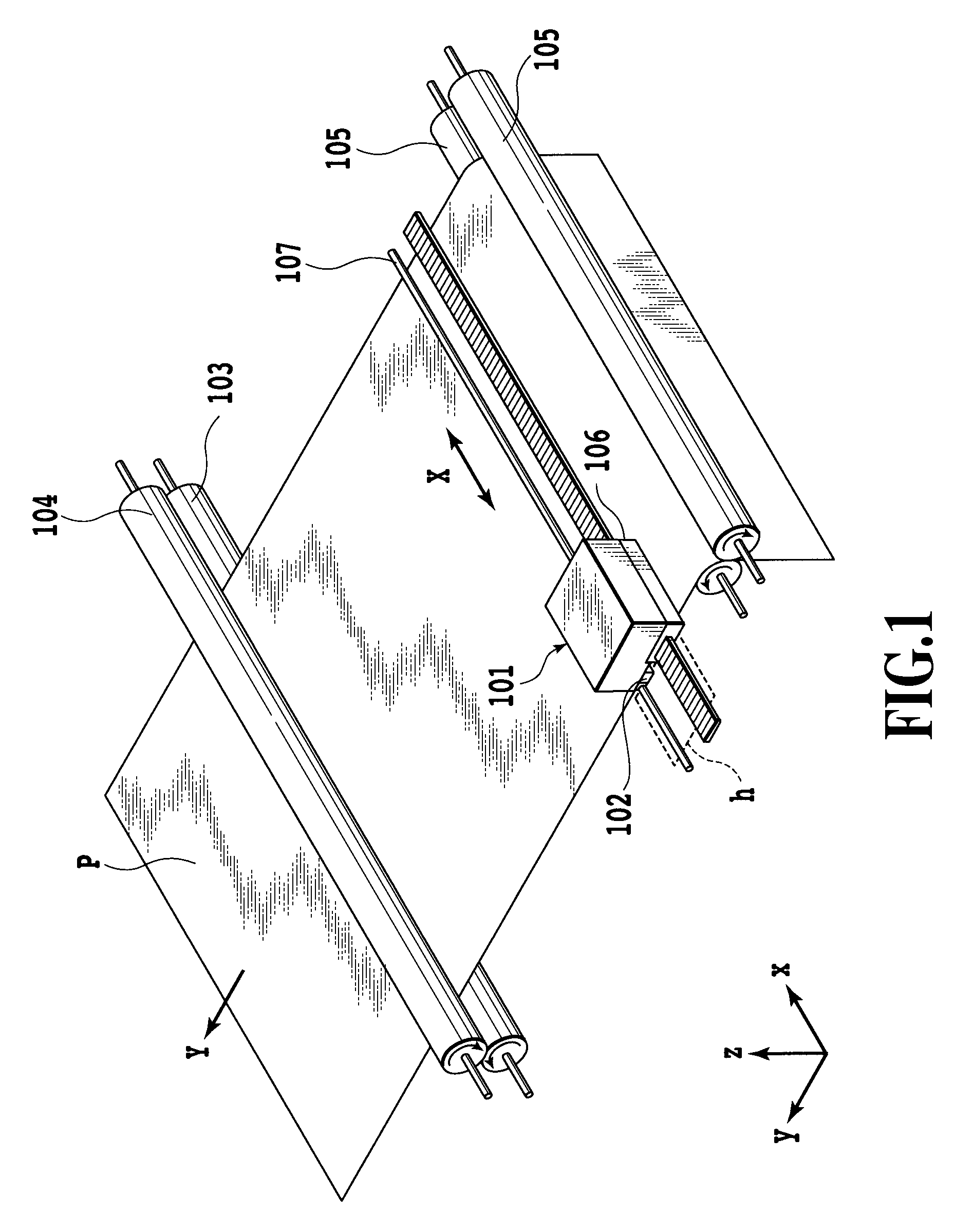
[0044]FIG. 1 is a schematic perspective view of a serial type ink jet printing apparatus capable of applying the present invention. The serial type ink jet printing apparatus forms an image on a print medium P by repetitively performing a printing scan operation of an ink jet print head 102 and a feed operation of the print medium P. The printing scan operation is an operation (main scanning) that causes the print head 102 to eject ink from its nozzle openings while moving the print head 102 in a main scan direction indicated by arrow X. The feed operation is an operation (sub scanning) that moves the pri...

second embodiment

[0109]The print head 102 in the first embodiment described above has the nozzle array 401 comprised of eight nozzle openings 501 each capable of ejecting about 5 pl of ink at a time, as shown in FIG. 4.

[0110]FIG. 14 shows a schematic view of the print head 102 of this embodiment, which is formed with a nozzle array 401 and a nozzle array 1401. The nozzle array 401 comprises eight nozzle openings (first nozzle openings) 501 each capable of ejecting ink droplets of about 5 pl (first volume). The nozzle array 1401 comprises eight nozzle openings (second nozzle openings) 1501 each capable of ejecting ink droplets of about 2 pl (second volume).

[0111]FIG. 15 is a cross section of the nozzle array 1401 with the nozzle openings 1501 ejecting ink from the back of the sheet of this drawing toward the front. The nozzle openings 1501 each have an opening area through which 2 pl of ink droplet can be ejected. That is, they are each formed circular 10.4 μm in diameter. The dimensions of bubble ch...

third embodiment

[0119]The print head in the first and second embodiments uses electrothermal conversion elements (heaters) as ink ejection energy generation elements (print elements). The print elements may also be constructed of piezoelectric elements. In that case, it is necessary to have a heating element to raise the temperature of ink in the print head.

[0120]The print head 102 of this embodiment has a warming heater 1702 separate from the print elements, as shown in FIG. 17. In FIG. 17, a nozzle array 401 is shown to comprise eight nozzle openings 501 each capable of ejecting 5 pl of ink. Arranged to surround the nozzle array 401 is the warming heater 1702. The heating of ink by the warming heater 1702 is also referred to as a “warming by heater”.

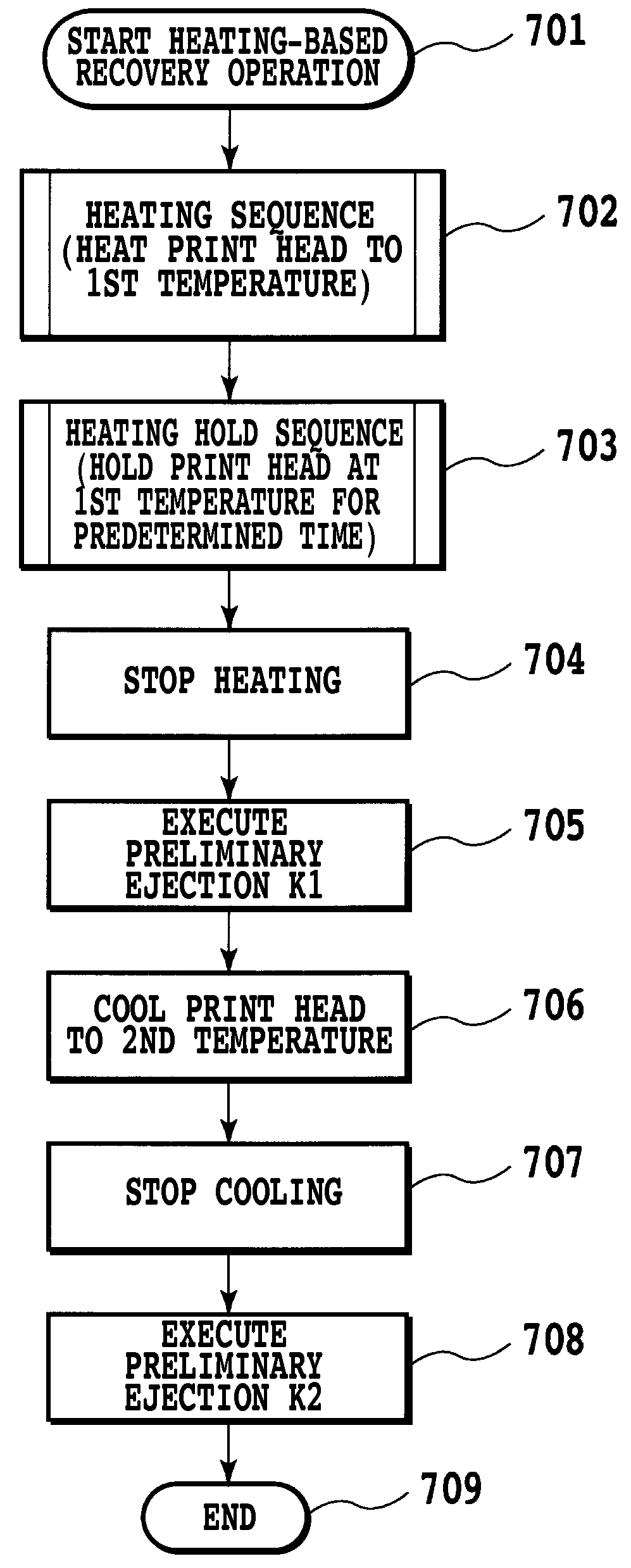
[0121]In this embodiment also, as in the preceding embodiments, the print head was subjected to the heating-based recovery operation of FIG. 7 to check how well the ejection performance of the print head was restored.

[0122]The heating-based recovery o...


PUM


Abstract

An ink jet printing apparatus and a print head recovery method are provided which effectively execute a preliminary ejection to eject ink not contributing to image printing from nozzle opening of the print head to maintain the ink ejection performance in good condition. The ink in the print head is heated to a first temperature, at which a first preliminary ejection is executed. Then, when the ink temperature falls to a second temperature, which is lower than the first temperature, a second preliminary ejection is executed.

Description

BACKGROUND OF THE INVENTION[0001]1. Field of the Invention[0002]The present invention relates to an ink jet printing apparatus to print an image using an ink ejection print head and a recovery method to keep an ink ejection performance of the print head in good condition.[0003]2. Description of the Related Art[0004]A recovery operation to keep the ink ejection from nozzle openings of the print head in normal condition has conventionally been performed in ink jet printing apparatus. The recovery operation can discharge viscous ink and minute ink bubbles from the print head and remove foreign matters and ink mist adhering to a surface of the print head where nozzle openings are formed. The recovery operation is known to include a suction operation, a preliminary ejection operation, a wiping operation and a heating operation, for example.[0005]Ink bubbles, when formed in the nozzle openings of the print head in particular, may cause ink ejection anomalies, such as ink ejection failures...

Claims


Application Information

Patent Timeline
IPC IPC(8): B41J29/38
CPCB41J2/04528B41J2/04563B41J2/04598B41J2/04588B41J2/0458
Inventor YAMAMOTO, WAKAKOKANDA, HIDEHIKOTANAKA, HIROKAZUOONUKI, KENICHI
Owner CANON KK
Why Eureka
Try Eureka