Optical system, method for focusing, and imaging apparatus equipped therewith
- Summary
- Abstract
- Description
- Claims
- Application Information
AI Technical Summary
Benefits of technology
Problems solved by technology
Method used
Image

Examples
first embodiment
[0031]An optical system according to a first embodiment of the present application is explained below.
[0032]An optical system according to the first embodiment includes, in order from an object, a first lens group having positive refractive power, and a second lens group having positive refractive power. The second lens group is movable along an optical axis for varying focusing. The first lens group satisfies the following conditional expression (1):
2.50<f1 / f (1)
where f1 denotes a focal length of the first lens group, and f denotes a focal length of the optical system.
[0033]With this lens configuration and satisfying conditional expression (1), it becomes possible to suppress various aberrations generated in the first lens group, so that excellent optical performance can be obtained.
[0034]Conditional expression (1) defines a ratio of refractive power of the first lens group to that of the optical system.
[0035]With satisfying conditional expression (1), when the focal length of...
example 1
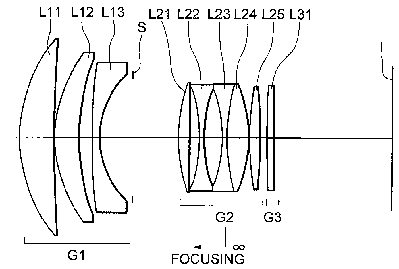
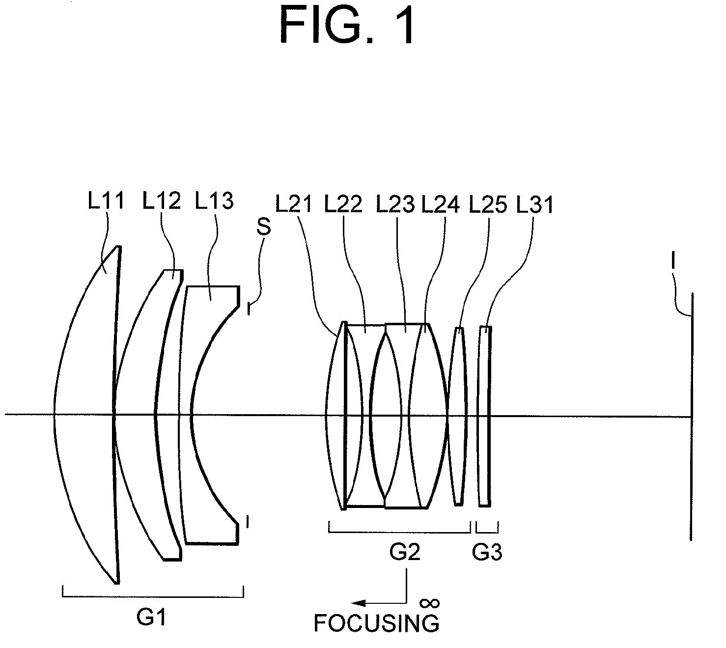
[0077]FIG. 1 is a sectional view showing a lens configuration of an optical system according to Example 1 of the first embodiment.
[0078]The optical system according to Example 1 includes, in order from an object, a first lens group G1 having positive refractive power, a second lens group G2 having positive refractive power, and a third lens group G3 having positive refractive power.
[0079]An aperture stop S is disposed between the first lens group G1 and the second lens group G2.
[0080]The first lens group G1 is composed of, in order from the object, a positive meniscus lens L11 having a convex surface facing the object, a positive meniscus lens L12 having a convex surface facing the object, and a negative meniscus lens L13 having a convex surface facing the object.
[0081]The second lens group G2 is composed of, in order from the object, a positive meniscus lens L21 having a convex surface facing the object, a double concave negative lens L22, a cemented lens constructed by a double co...
example 2
[0094]FIG. 3 is a sectional view showing a lens configuration of an optical system according to Example 2 of the first embodiment.
[0095]The optical system according to Example 2 includes, in order from an object, a first lens group G1 having positive refractive power, a second lens group G2 having positive refractive power, and a third lens group G3 having positive refractive power.
[0096]An aperture stop S is disposed between the first lens group G1 and the second lens group G2.
[0097]The first lens group G1 is composed of, in order from the object, a positive meniscus lens L11 having a convex surface facing the object, a positive meniscus lens L12 having a convex surface facing the object, and a negative meniscus lens L13 having a convex surface facing the object.
[0098]The second lens group G2 is composed of, in order from the object, a positive meniscus lens L21 having a convex surface facing the object, a double concave negative lens L22, a cemented lens constructed by a double co...
PUM
 Abstract
Description
Claims
Application Information
 - Generate Ideas
- Intellectual Property
- Life Sciences
- Materials
- Tech Scout
- Unparalleled Data Quality
- Higher Quality Content
- 60% Fewer Hallucinations
Browse by: Latest US Patents, China's latest patents, Technical Efficacy Thesaurus, Application Domain, Technology Topic, Popular Technical Reports.
© 2025 PatSnap. All rights reserved.Legal|Privacy policy|Modern Slavery Act Transparency Statement|Sitemap|About US| Contact US: help@patsnap.com