Dental tool

a technology for teeth and mouth, applied in dental tools, dental surgery, medical science, etc., can solve the problems of prosthetic removal, loss of teeth, and loss of teeth, and achieve the effect of convenient and safe removal of prosthetics or appliances, and convenient and safe grip

Inactive Publication Date: 2009-10-01
CREASMAN SUSAN M +1
View PDF24 Cites 21 Cited by
  • Summary
  • Abstract
  • Description
  • Claims
  • Application Information

AI Technical Summary

Benefits of technology

[0011]The present invention is directed to a hand held dental tool that satisfies the need to overcome dental prosthetic and appliance retention forces to easily and safely remove the prosthetic or appliance. The hand held dental tool comprises a handle that facilitates a sturdy grip and an engagement head

Problems solved by technology

However, over the centuries, humans have been contending with the loss of some or all of their teeth as a result of accidents, injuries, or oral disease, and the loss of teeth remains a problem to this day in spite of the advances of modern dental medicine.
These initial attempts at dental prosthetics, while an improvement over having no teeth, suffered from the problem of retention, or more specifically, how well the denture is prevented from moving in the vertical plane in the opposite direction of insertion.
Further, after a person has used dentures for a time period, the underlying bone in the person's jaw, and more specifically the alveolar bone in which the teeth normally reside, has tended to shrink and atrophy thereby causing well fitting dentures to now become ill fitting dentures with an undesirable decrease in retention.
Concurrent w

Method used


Image

  • Dental tool
  • Dental tool
  • Dental tool

Examples


embodiment 420

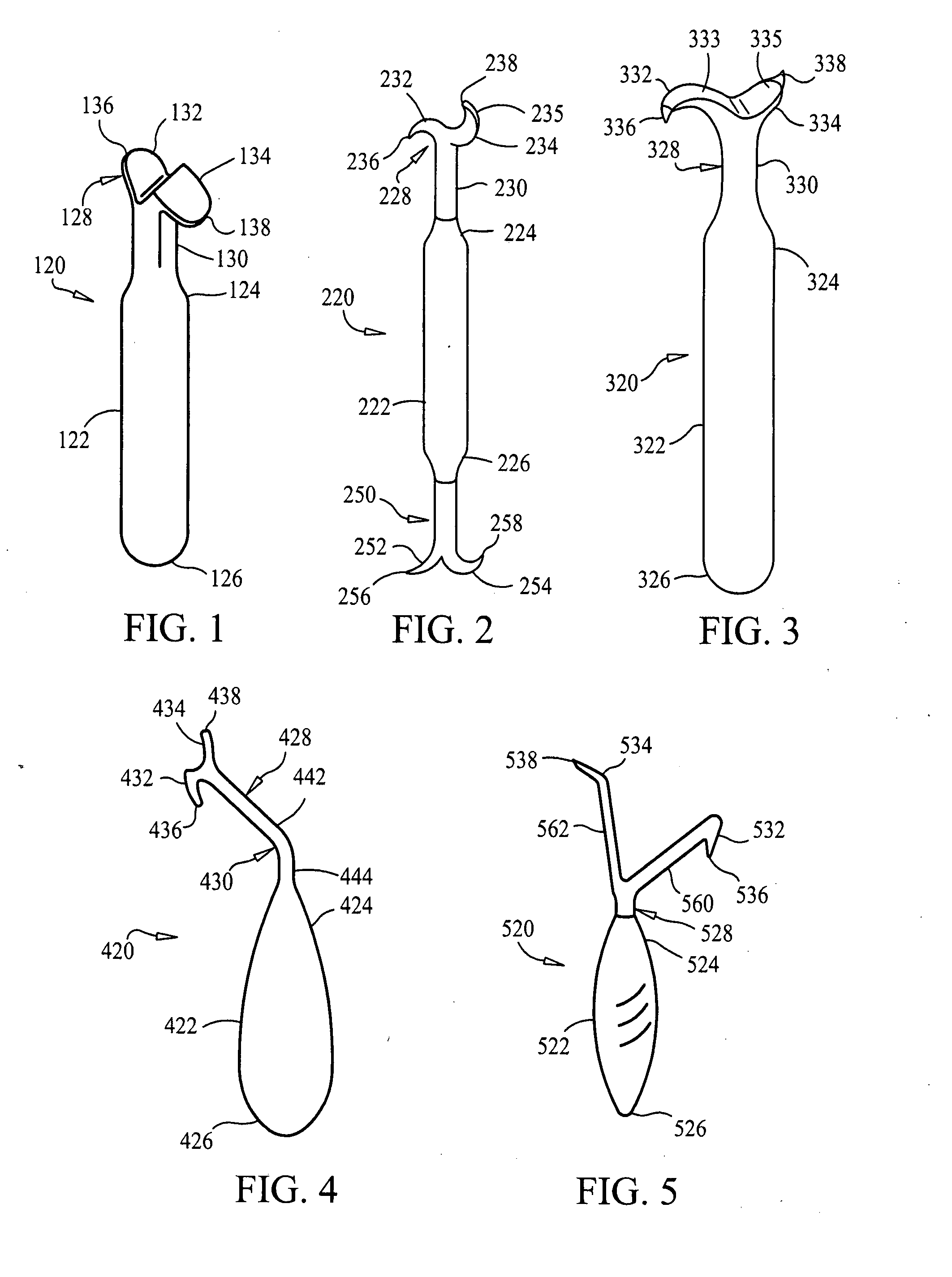
[0035]Turning to FIG. 4, dental tool embodiment 420 has an ergonomically teardrop shaped handle 422 having a first small end 424 to which engagement head 428 is affixed and a large second end 426 that more comfortably fits within the grasp of a user than a handle having a cylindrical configuration. Neck 430 of engagement head 428 has two segments 442 and 444 that are angularly arranged one with respect to the other. The angular arrangement of neck segments 442 and 444 facilitates a user holding handle 422 in a more comfortable position while simultaneously permitting fingers 432 and 434 to engage a dental prosthesis at an optimal angle. Downwardly extending finger 436 and upwardly extending finger 434 can be generally circular in cross-section and terminate at tips 436 and 438 that generally spherically configured to prevent injury to the mucosal layer underlying the dental prosthesis to be removed with dental tool 420.

embodiment 520

[0036]Dental tool embodiment 520 as shown in FIG. 5 has a handle 522 with an alternate ergonomic configuration having ends 524 and 526 wherein engagement head 528 is affixed to handle end 524. Engagement head 528 has a bifurcated neck comprising first and second arms 560 and 562 arranged at an angle one to the other. First arm 560 includes first downwardly extending finger 532 terminating at tip 536 for engaging an upper dental prosthesis to be removed. In like manner, second arm 562 includes second upwardly extending finger 534 terminating at tip 538 for engaging a lower dental prosthesis to be removed.

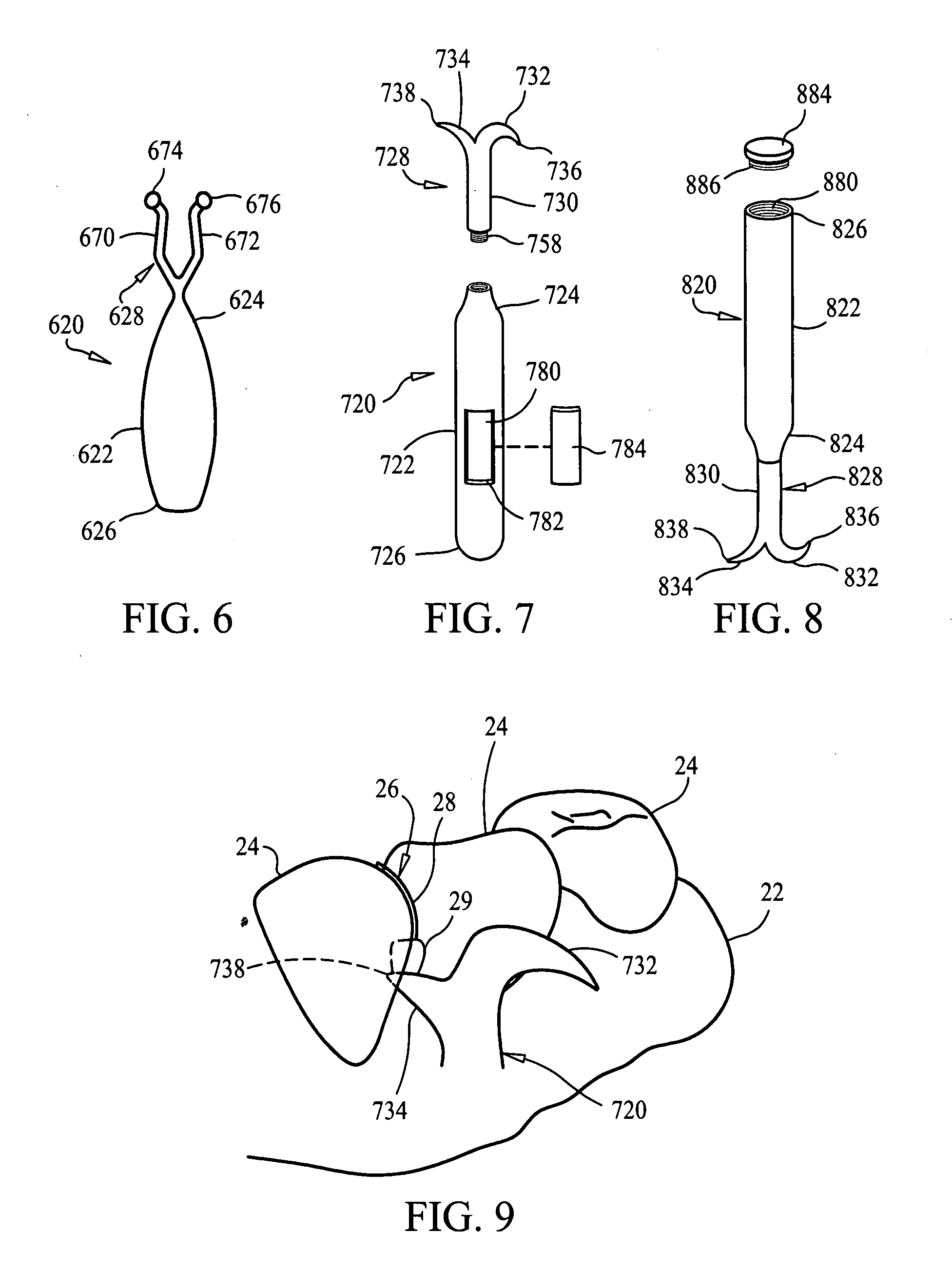
[0037]Turning to FIG. 6, an alternate embodiment dental tool 620 is illustrated with an ergonomic handle having ends 624 and 626 wherein an engagement head 628 is affixed to end 624. Engagement head 628 includes spaced apart arms 670 and 672 wherein arms 670 and 672 terminate with resilient suction cups 674 and 676 respectively for engaging a dental prosthesis. The suction cups 674 a...

embodiment 720

[0038]FIG. 7 shows a dental tool embodiment 720 wherein handle 722 is formed such that it defines an internal void 780 that is accessible through aperture 782 which receives a removable panel 784. In this manner, handle 722 can be utilized for storage. Additionally, engagement head 728 can be removable from handle 722. Engagement head 728 has an engagement feature 758 such as threads or a snap-in retaining feature known in the art at an end of neck 730 which is received in end 724 of handle 722. Engagement head 728, like those previously, includes an upwardly extending finger 734 terminating at tip 738 and a downwardly extending finger 732 terminating at tip 736.

[0039]FIG. 8 illustrates an alternate embodiment dental tool 820 similar to dental tool 720 wherein handle 822 defines an internal void 880 which is accessible by removable end cap 884 at handle end 826. End cap 884 includes an engagement feature 886 such as threads or a snap-in retaining feature known in the art. Dental too...


PUM


Abstract

A hand held dental tool for removing dental prostheses and dental appliances from a user's mouth comprises a handle that facilitates a sturdy grip and an engagement head affixed an end of the handle for engaging the prosthesis of appliance. The engagement head has dual fingers extending oppositely away from the head wherein a first finger extends upwardly from the head and a second finger extends downwardly from the head for engaging lower and upper prostheses respectively.

Description

CROSS-REFERENCE TO RELATED APPLICATION[0001]This application claims the benefit of co-pending U.S. Provisional Patent Application Ser. No. 60 / 875,904, filed on Dec. 20, 2006, which is incorporated herein in its entirety.BACKGROUND OF THE INVENTION[0002]1. Field of the Invention[0003]The present invention relates to dental instruments in general and more particularly to dental instruments to aid in the removal of dental appliances.[0004]2. Discussion of the Related Art[0005]Dental hygiene and tooth maintenance is a very important part of everyday life. Healthy teeth are not only aesthetically pleasing, but are also a necessary and vital part of our daily routine of food consumption. A full set of teeth allow us to chew our food to aid in the digestive process, thus we place a high emphasis dental care to retain as many of our natural teeth as possible. However, over the centuries, humans have been contending with the loss of some or all of their teeth as a result of accidents, injuri...

Claims


Application Information

Patent Timeline
IPC IPC(8): A61C3/00
CPCA61C7/02A61C3/00
Inventor CREASMAN, SUSAN M.CREASMAN, DEBORAH E.
Owner CREASMAN SUSAN M
Why Eureka
Try Eureka